4. Windowless Extended Gas Target
This chapter presents a summary of the setup and operation of SECAR’s extended gas target.
4.1. Introduction
SECAR has two gas targets:
The Jet Experiments in Nuclear Astrophysics (JENSA)
The windowless extended gas target
Each of these targets has its own configuration, and the target chambers and associated hardware are very different from one another. However, they both use the same Gas Handling System (GHS). Currently, the windowless extended gas target is the only SECAR’s target whose operation is fully automatic except the operation of the high vacuum pumps. This target typically runs the gas in recirculating mode (see Fig. 4.12).
This chapter presents the windowless extended gas target.
Note
Hydrogen operation is currently not authorized and is in the near future only forseen with the extended gas target.
4.2. Emergency response
If in an emergency situation (such as a building evacuation or a shelter in place order) the gas target needs to be left anattended for an extended period of time, use the following procedures to bring it into a safe state:
For He operation follow: Emergency Response Procedxure for SECAR Extended and Jet Gas Targets During Helium Operation.
4.3. Accessing CS-Studio Control Page for Both SECAR’s Gas Targets
The SECAR’s gas targets controls can be found here:
On a computer connected to the NSCL (CTL) controls network, open CS-Studio. Go to File, Top Files, NSCL, and open SECAR tab. Then, a window opens which is called SECAR Global Controls. From the top of that page, click on “JENSA …” button and then click on Target GHS. A new window opens called
Main.opi. This is where the controls of the SECAR’s gas targets can be found (see Fig. 4.1).
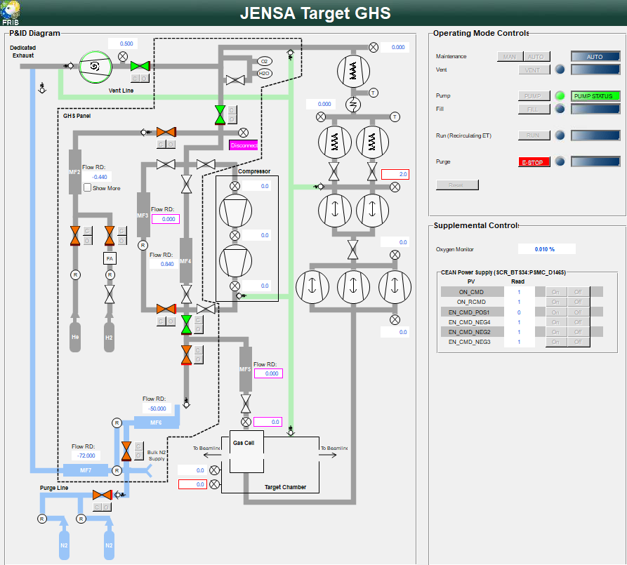
Fig. 4.1 The CS-Studio control page for both SECAR’s gas targets. MF5 is only used for the jet target’s operation.
The symbols on this page are shown in the table below:
Symbol |
Meaning |
|
Valve is open |
|
Valve is closed |
|
Controls for opening (o) and closing (c) valves |
|
Manual valve (locked in its state until manually changed |
|
Scroll pump in ON |
|
Scroll pump is OFF |
|
Capacitance manometer gauge and its readback value in Torr |
|
Pressure reliefe valve |
|
Oxygen sensor |
|
Humidity sensor (not used) |
|
Mass flow meter |
|
Flow readback in sccm (standard cubic centimeter per minute |
|
Pressure regulator |
|
DV650 Screw pump |
|
Roots blower pump |
|
Turbo pump |
|
Heat exchanger |
|
Thermometer |
|
Gas supply - This one contains hydrogen |
|
JENSA Compressor head |
|
Flash arrestor |
|
Selected operating mode |
|
Emergency stop |
|
Reset button |
|
ON/OFF control buttons for the main CAEN power supply |
|
ON/OFF control buttons for the positive HV card |
|
ON/OFF control buttons for the negative HV cards |


4.3.1. P&ID Diagram
The left side of the Main.opi page in CS-Studio (see Fig. 4.1) contains the schematics of all the hardware controls located on the gas handling system of the extended gas target. These can be commanded either manually (when switched to MAN operating mode control) or automatically (when switched to any other operating mode control).
Figure below shows the extended gas target’s gas handling system more clearly.
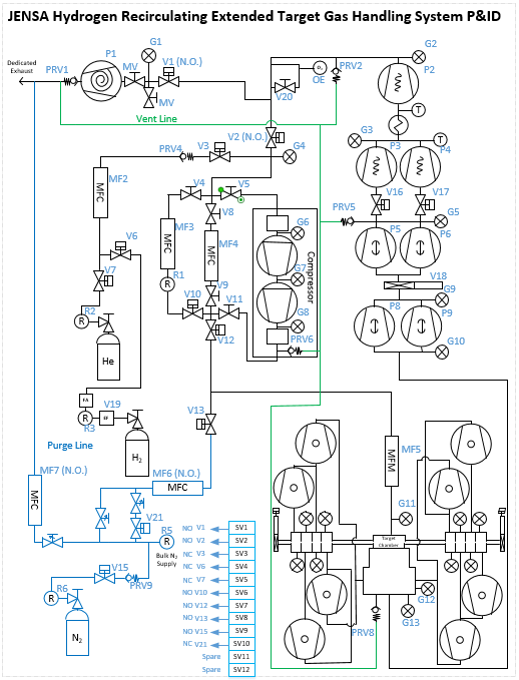
|
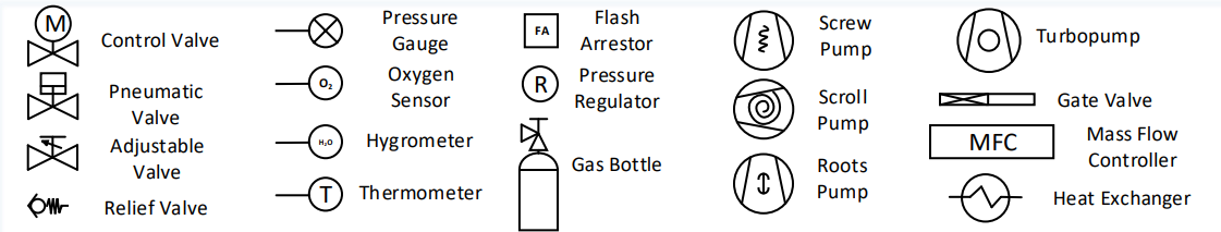
Fig. 4.2 The extended target’s gas handling system’s P&ID. NO and NC indicate normally open and normally closed, respectively. This target is only operated in recirculating mode. |
On Fig. 4.1, an orange valve ( ) indicates it is closed, and a green valve (
 ) indicates it is open. Those valves which can only be operated fully manually are shown in Fig. 4.1 by a white color (
 ).
).
4.3.1.1. How to Operate the Manual Valves on the GHS
These valves are locked into their state and have to first be unlocked before changing their state. There is a metallic padlock visible on the body of these valves. To unlock the valve, push that padlock down (if it is on the top of the valve) or up (if it is on the bottom of the valve) and then rotate the valve (can only rotate in one direction) while you are pressing the metallic padlock to change the valve’s state. It will be locked again once you release the padlock. These valves allow easy switch between extended gas target and jet target configurations. Their status (open vs. closed) is locked during operation.
4.3.1.2. How to Operate the Mass Flow Meters of the GHS
MFs are Mass Flow meters, also called Mass Flow Controllers (MFCs), which are devices to control the flow rate of the process gas. The MF have three modes: OPEN, CLOSE, and SETPOINT:
OPENcreates a maximum opening without any defined flow, for example for pumping the system outCLOSEcloses the MF so no gas can flow throughSETPOINTallows the user to set a flow rate that is then maintained (if possible). There is a maximum setpoint defined that may have been set based on safety or engineering considerations. Note that setting the MF to the maximum flow rate in SETPOINT mode is NOT the same as setting it to OPEN mode.
To operate the MFs
To view and set the mode of a MF one currently needs to use the PV Probe functionality: Right click on the flow display field (not the MF), select “Probe”, and in the window that is popping up enter the PV for setting the mode - replace the text after the “:” (usually F_RD) with
MODE_CSET_MFC. You may need to wait a bit for the current mode to be displayed as value. You can then change the mode by entering either OPEN, CLOSE, or SETPOINT.To view and adjust the flow, right click on the MF symbol on the controls page and select “Open Mass Flow Controller Details”. A small window pops up that allows to view and set the current flow. Note that this only makes sense in
SETPOINTmode, however, currently this window also displays something in the other modes, with no indication that its not meaningful.
Warning
It is highly recommended to not set the gas supply mass flow meter (MF2) to Set to OPEN because it might fill the system with a lot of gas too quickly and the fill volume will not be integrated accurately in that case. Setting MF2 to Set to OPEN is not the same as setting its set point to 100 sccm, which is the maximum flow delivered by MF2. The orifice of the mass flow meter will be fully opened if it is set to OPEN and the flow rate will not be known precisely. It may flood the system with gas so please avoid setting it to Set to OPEN.
The default state of valves and MFs are shown in the Table 4.2. The state of the manual valves during operation of the extended gas target is also shown in this table.
Device |
Default State |
Device |
Default State |
V1 |
NO |
V15 |
NO |
V2 |
NO |
V16 |
NO |
V3 |
NC |
V17 |
NO |
V4 |
Manual and closed |
V18 |
Manual and open |
V5 |
Manual and closed |
V19 |
Manual (see text) |
V6 |
NC |
V20 |
Manual and open |
V7 |
NC |
V21 |
NC |
V8 |
Manual and open |
MF2 |
NC |
V9 |
Manual and open |
MF3 |
NC |
V10 |
NO |
MF4 |
NO |
V11 |
Manual and closed |
MF5 |
NO |
V12 |
NO |
MF6 |
NO |
V13 |
NO |
MF7 |
NO |
V14 |
Manual (see text) |
Note
V4,V5andV11valves should remain closed during the operation of the extended gas target. These valves are only used when the jet taret is in use.V5is the valve that allows the supply gas to flow from the gas handling system to the inlet of the JENSA compressor.V11is the valve that allows the high pressure processed gas to flow from the outlet of the JENSA compressor to the gas handling system.V4is the valve that needs to be opened for the gas to flow in the jet bypass loop.V14, which is currently not installed, is the valve that allows the jet to flow into the jet gas target’s chamber.V8andV9valves should remain open during the operation of the extended gas target.V14is currently not installed. This is a manual valve with a green handle that was previously labelled as \(V_{in}\). This valve is only used with the jet target and will be only opened during the last steps of turning ON the jet to allow the jet to flow inside the jet target chamber.V18is a manual gate valve shown in Fig. 4.3. This valve should always be open unless in special circumstances such as leak checking to isolate the target section from the pumps underneath the JENSA noise enclosure.V19is the Parker excess flow valve shown in Fig. 4.4. It should be closed when hydrogen bottle is not installed or when an empty hydrogen bottle is being exchanged with a new filled bottle. All other times, this valve should be open.V20is a manual valve shown in Fig. 4.5. This valve should remain open during the operation of the extended gas target.
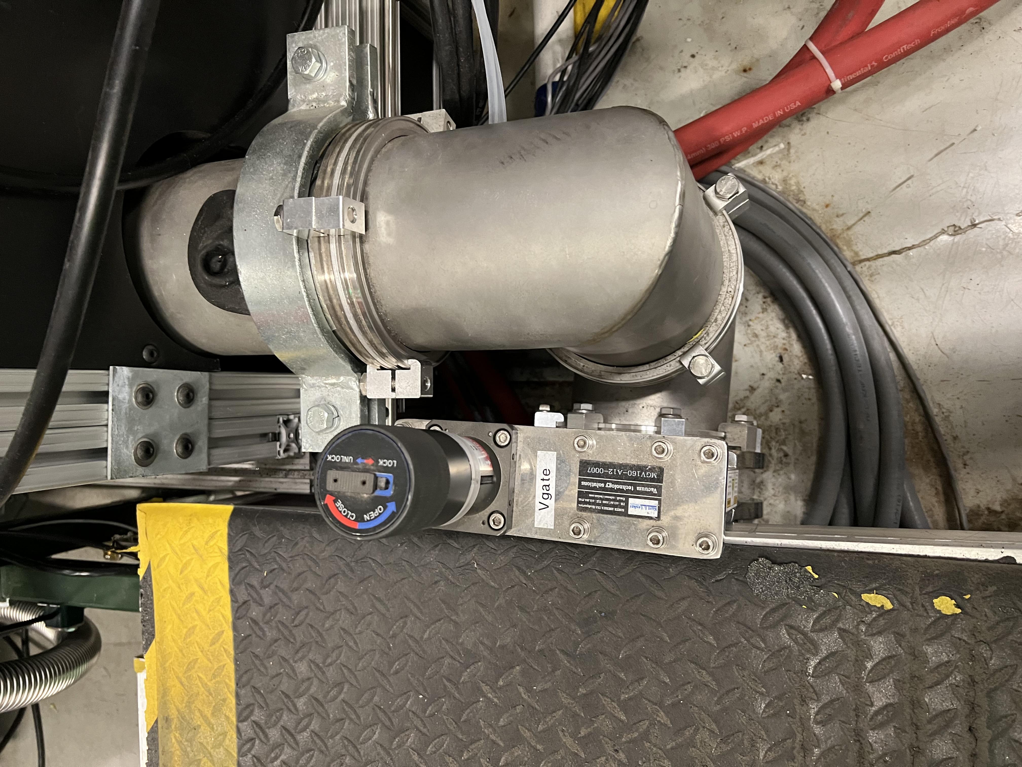
Fig. 4.3 The manual gate valve V18 that separates the target area from the DV650 pumps underneath the JENSA compressor’s noise enclosure.

Fig. 4.4 The Parker excess flow valve (V19) automatically stops the flow if it is above 40 standard liters per minute.
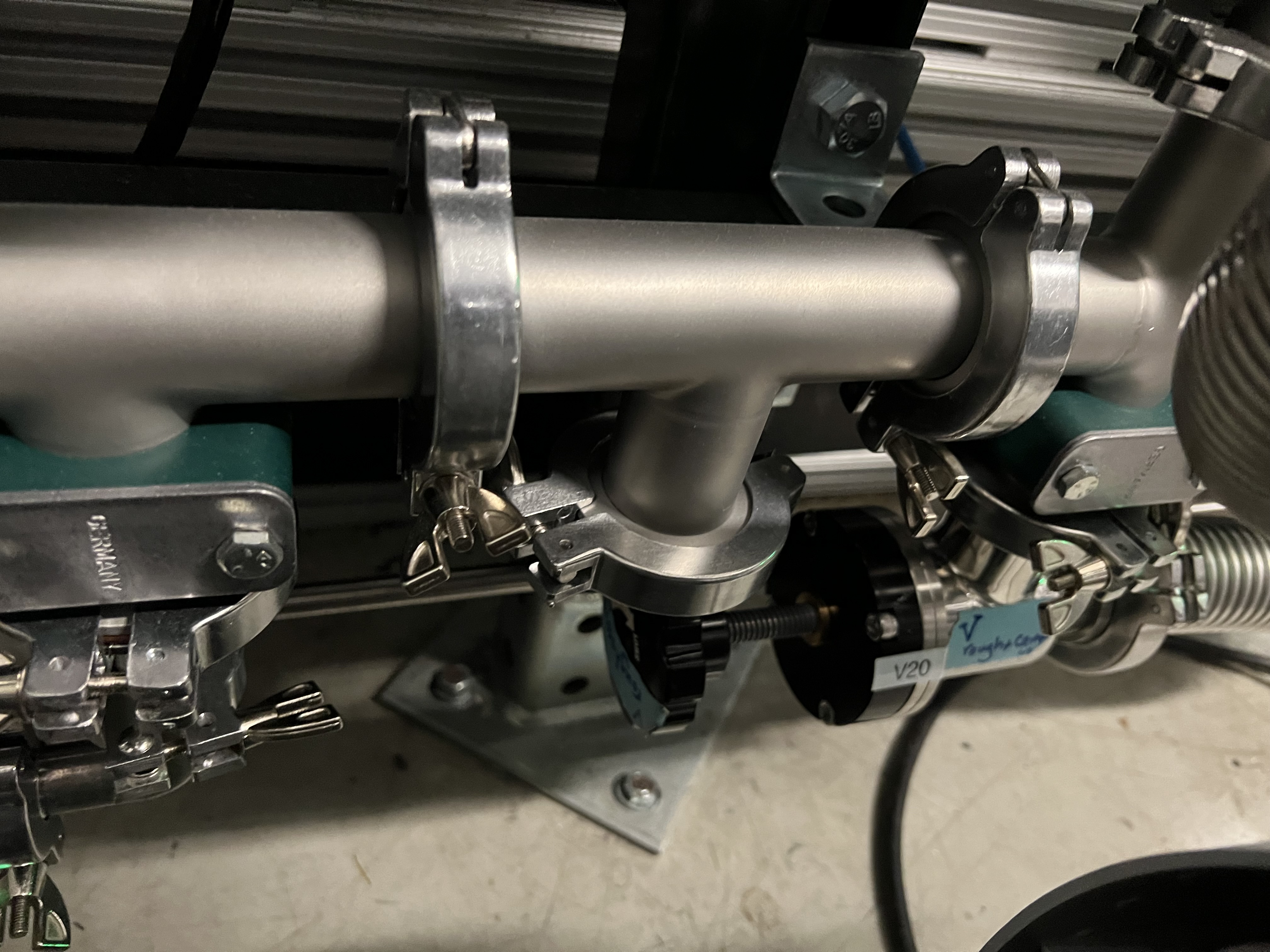
Fig. 4.5 This manual valve V20 is near the ground behind the roughing pump on the gas handling system’s panel. It is also called Vrough+copmin
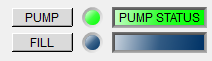
4.3.2. Operating Mode Controls
This section presents a summary of the operating modes of the SECAR’s targets’ GHS. A more detailed section on each operating mode will follow later.
The right side of the Main.opi page in CS-Studio (see Fig. 4.1) contains the operating mode controls. These are various available modes of operation described below:
MANmode of operation: this mode is activated when clicking on theMANbutton seen on the top left hand side of Fig. 4.1. This mode of operation is used for maintenance, operation of JENSA jet target, gas bottle exchange, and long term system idle. This is the only mode of operation in which valves are commanded manually by the operator via the control software so it requires expert knowledge of the system. The valves can be opened in this mode of operation by clicking on the “o” button near a valve to open that valve, or by clicking on the “c” button near a valve to close it ( ). Manual mode of operation needs to be “turned off” (by switching to
 Automode, see below) before switching into any other mode of operation.
Turning off the
MANmode is performed by clicking on theAutobutton seen on the top left hand side of Fig. 4.1. TheAutomode contains all other operating modes where the control is all automatic, and the change in the states of valves is performed by the control software depending on which mode of operation is chosen. WhenAutobutton is clicked, all valves switch to their default states (see Table 4.2): all valves exceptV3,V6,V7, andV21are normally open.V3,V6,V7andV21are normally closed. All MFs are normally open exceptMF2andMF3, which are normally closed. This means that after clicking on theAutobutton, every valve will be opened exceptV3,V6,V7, andV21, which will be closed. Therefore, when the system is under high vacuum with the high vacuum pumps running, if you have to switch to manual mode of operation for some reason, make sure you quickly click on pump mode of operation very soon after clicking on theAutobutton to avoid filling the system with nitrogen that will enter the system throughMF6and valvesV12andV13, which will be open when you switch toAutomode.
Danger
There is a needle valve associated with mass flow meter MF6. This needle valve is shown in Fig. 4.6. It is upstream MF6 (on the path of \(N_{2}\) gas for purging) and is already set to only allow a nitrogen flow of 1000 sccm through the MF6 flow meter for purging the system. Please do not touch this valve to avoid changing the flow that is set. This specific flow is set to a low rate to avoid loading and harming the turbo pumps during the operation of the gas target in purge mode. For the same reason, please esnure that MF6 is set to have 1000 sccm flow set point unless when you are venting the system.
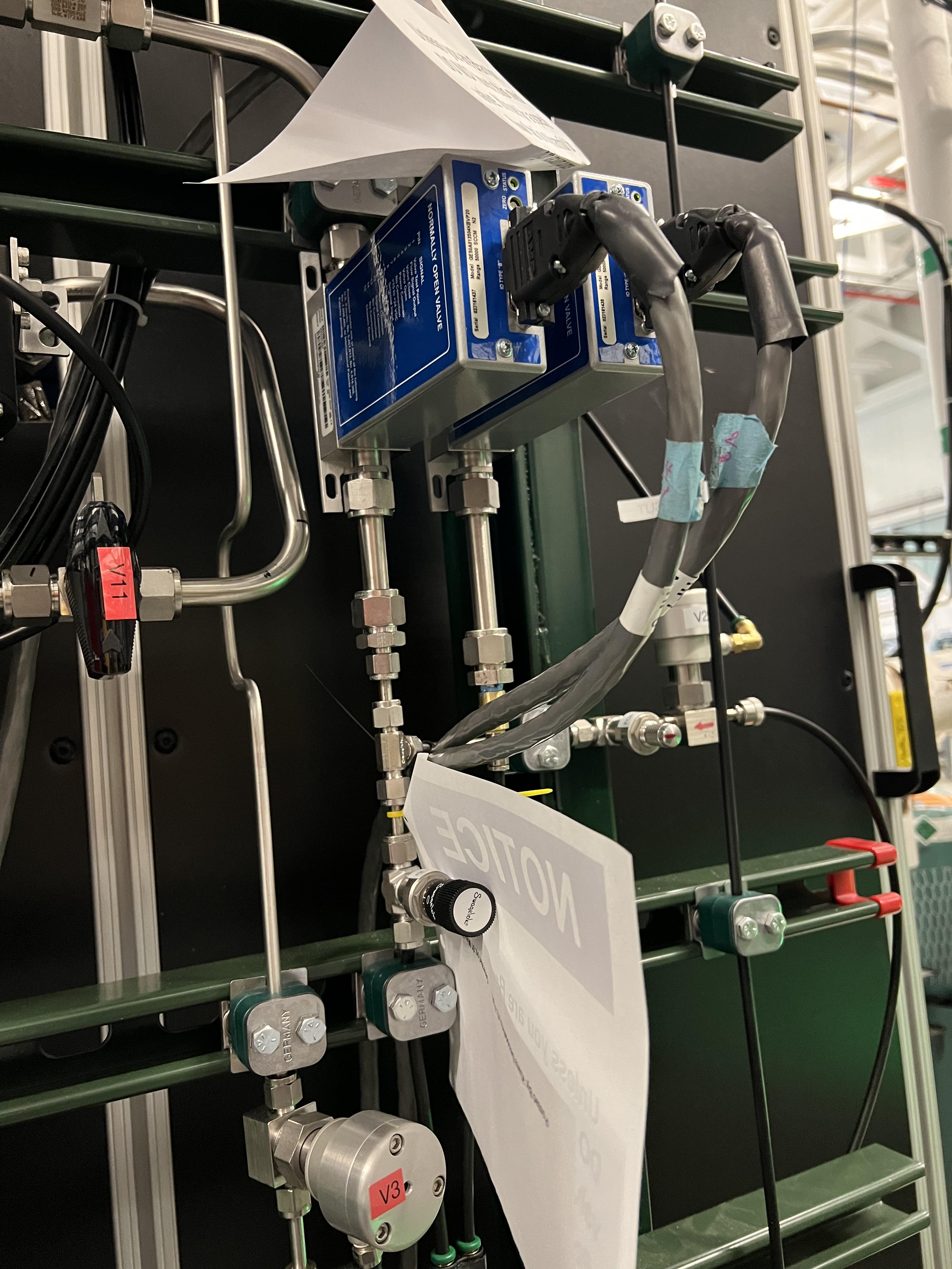
Fig. 4.6 The needle valve underneath the two mass flow meters shown in the photo is labelled as “For MF6”. It is upstream MF6 (on the path of \(N_{2}\) gas for purging) and is already set to only allow a nitrogen flow of 1000 sccm through the MF6 flow meter for purging the system. Please do not touch this valve to avoid changing the flow that is set. This specific flow is set to a low rate to avoid loading and harming the turbo pumps during the operation of the gas target in purge mode. For the same reason, please esnure that MF6 is set to have 1000 sccm flow set point unless when you are venting the system.
Ventmode of operation: this is used for venting the system. Once vent mode is initiated, the system is fully remote controllable and the control software will closeV1and opensV13. ValvesV3,V6,V7, andV10remain closed, while valveV12remains open. The operator can open valveV21if she/he desires only while the system is inventorMANmode of operation. This mode automatically turns OFF the scroll pump (see Fig. 4.7).

Fig. 4.7 The schematics of vent mode of operation. Image courtesy of Brandon Ewert.
Warning
If the high vacuum pumps (turbo pumps, Roots blowers, and DV650 pumps) are running, the operator has to make sure all these pumps and all 8 cold cathode gauges are turned off before switching to the vent mode. These pumps are all manually controlled via their associated controllers inside the ReA3 vault, so the operator has to ensure it is safe to re-enter the vault (Section 4.7.6) if the gas target is running hydrogen.
Attention
While in vent mode of operation, when the capacitance manometers of the system show around 730 – 760 torr, the operator should switch to the
MANmode of operation and closeV13andV21valves. The pressure relief valves (see Fig. 4.8) in the system will avoid over pressurizing the system (see the vent line in Fig. 4.7). But bothV13andV21valves should be closed manually (by switching to theMANmode of operation and commanding the valves closed) when the system is fully vented.Also, the operator should close the manual roughing valve (labelled as
VROUGH, see Fig. 4.9) located on the JENSA scroll pump for the safety of the scroll pump in case the target chamber is opened to air and there may be a large leak the next time the system is put in pump mode.Note that when the system is fully vented, the pressure inside the gas target read by capacitance manometer G11 (
SCR_BTS34:CMG_D1465K) reaches 100 Torr maximum because this manometer is only capable of reading maximum of 100 Torr. The minimum is 1 Torr. Similarly, the pressure read by capacitance monometer G13 (SCR_BTS34:CMG_D1465M) only reads 1 Torr maximum and 10 mTorr minimum.
Fig. 4.8 The pressure reliefe valve is the tiny device seen on the right side of the KF-16 clamp. There are many such devices implemented in the gas handling system of SECAR targets and they are all tied to the flammable gas exhaust. Once the pressure at the foreline of the scroll pump reaches 1 atm., the pressure relief valve called PRV2 (see Fig. 4.7) opens to vent the overpressure to the flammable exhaust.
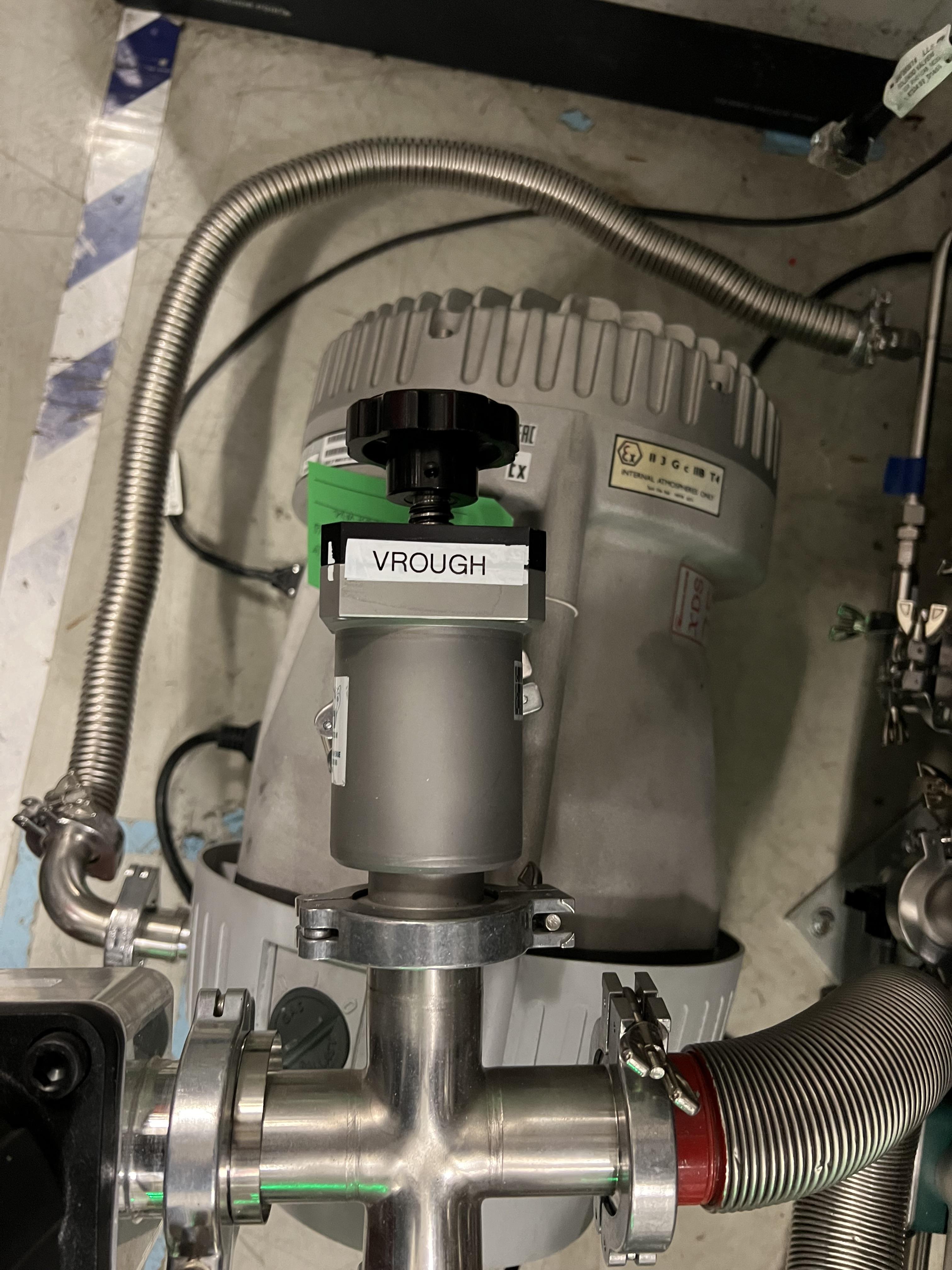
Fig. 4.9 The manual roughing valve on the JENSA scroll pump is labelled as VROUGH.
Danger
- Note that the only times when the system automatically switches to the vent mode of operation is when the system is in either in pump or in purge mode and the scroll pump loses power or fails for some other reason. In these cases, the control system automatically switches the operating mode to vent mode. In this case, it is crucial to ensure the high vacuum pumps are turned OFF manually and safely before the pressure rises above 55 – 60 Torr in the gas target. Vent mode is automatically triggered if:
Laboratory power is lost.
The scroll pump loses power while the system is in pump or purge mode of operation.
Pumpmode of operation: this is used for pumping down the system from atmosphere, or when the system is running under high or low vacuum idly and without any gas in the target system. While the system is inpumpmode, the system will be pumped at full speed via the scroll pump (and all other pumps if they are running). The scroll pump has a manual roughing valve labelled asVROUGH(Fig. 4.9). This valve should be fully opened. The operator can turn ON all the other pumps manually (requires presence in the ReA3 vault) when the system is in this mode of operation. Fig. 4.10 shows the schematics of the gas target while inpumpmode. In this mode, the control software turns the scroll pump ON, opensV1and closesV13. ValvesV2andV12remain open, while valvesV3,V6,V7, andV10remain closed.
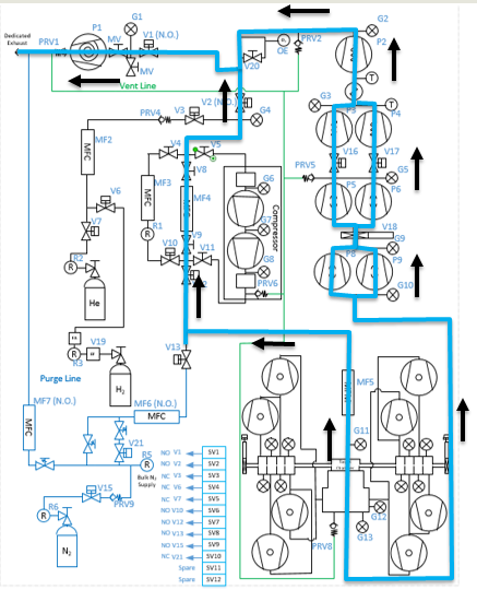
Fig. 4.10 The schematics of pump mode of operation. Image courtesy of Brandon Ewert.
Fillmode of operation: this is used when filling the gas target with a gas before recirculation of the gas is applied. Fig. 4.11 shows the schematics of this mode of operation. In this mode of operation, the control software closesV1and opensV3andV6orV7. ValvesV2, andV12remain open, whileV10andV13remain closed. All the high vacuum recirculating pumps should be fully running in this mode. The operator opensMF2to regulate and charge the system with the supplied gas (V6is open in case of a hydrogen fill,V7is open in case of a fill with He or another type of a non-explosive gas). Once the desired pressure in the gas chamber is reached as read by G11 capacitance manometer (SCR_BTS34:CMG_D1465K), the operator has to switch to therunmode.
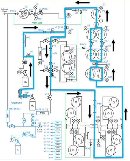
Fig. 4.11 The schematics of fill mode of operation. Image courtesy of Brandon Ewert.
Runmode of operation: in this mode of operation, the control software closesV3andV6orV7, whichever was being used. All other valves have the same state as they had in thefillmode.V2andV12valves remain open to establish flow (see Fig. 4.12).MF4should be adjusted to deliver the desired flow to the gas target and to keep the gas target pressure steady. Gas is recirculating through the system. Only in this mode of operation, the PIPS detectors inside the extended gas target can be biased only after theresetbutton on the operation mode section of the control page is clicked and if the oxygen level is below \(0.4 \%\), andSCR_BTS34:CMG_D1465K(G11) andSCR_BTS34:CMG_D1465M(G13) capacitance manometer gauges are reading below 25 Torr and 10 mTorr, respectively.
Warning
Make sure the pressure read by G3 capacitance manometer (SCR_BTS34:CMG_D1465C) does not exceed 210 Torr while the system is in run mode, or else the last DV650 pump will shut itself down. In reality, this pressure cannot be reached because there is an interlock on SCR_BTS34:CMG_D1465C (G3 gauge), which would switch the system into purge mode if this gauge reading reaches 20 Torr.

Fig. 4.12 The schematics of run mode of operation. Image courtesy of Brandon Ewert.
Purgemode of operation: This mode of operation (see Fig. 4.14) is triggered by software control if any of the interlocks are reached, or by the operator if he/she clicks on the emergency stop button on the control page ( ). The latter action is accessible from any mode of operation. In
 purgemode of operation, if hydrogen is the fill gas,MF7supplies a constant flow of dry nitrogen (with a rate of 1000 sccm preset by a needle valve upstreamMF7, see Fig. 4.13) to dilute the exhaust in case of an overpressure condition during the fill.MF6is opened to a safe (for high vacuum pumps that are running) flow rate of 1000 sccm preset by another needle valve upstreamMF6andV21(see Fig. 4.6) to purge the system with dry nitrogen from the lab supply of dry nitrogen. If the flow of dry nitrogen throughMF6drops below \(70\%\) of its set value (for example due to a failure of the laboratory dry nitrogen supply),V15opens automatically by the control software, and a dry nitrogen backup bottle kicks in to supply \(N_{2}\) and to continue purging the system with dry nitrogen. The JENSA scroll pump pumps the mixture of gas out, and hydrogen-nitrogen mixture is directed into the exhaust and is further diluted. In this mode of operation, the control system opensV13andV1. ValvesV2andV12remain open, while valvesV3,V6,V7, andV10remain closed.
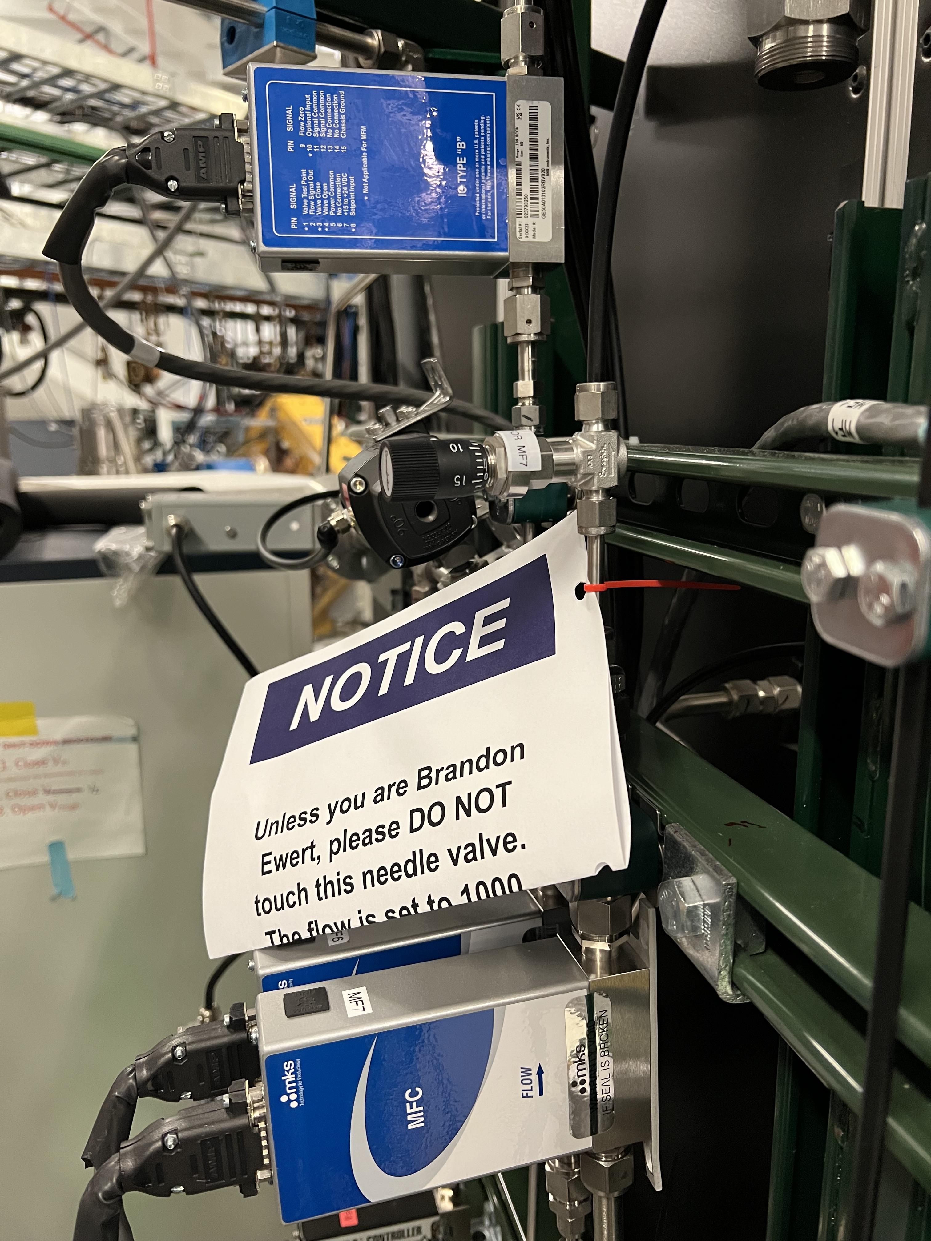
Fig. 4.13 The needle valve upstream of MF7, labelled as “For MF7”, is already set to only allow a dry nitrogen flow rate of 1000 sccm through MF7. Please do not touch this needle valve to avoid changing the preset flow through MF7. If you change the position of this needle valve, there will be too much dry nitrogen going in the exhaust, which will waste the nitrogen. Please also do not change the flow setpoint of MF7, which is set to 1000 sccm. The maximum flow rate for this mass flow meter is 50000 sccm, which is too much.
Note
After 10 minutes of purging, the operator has to click on  button first and then change the mode of operation to
 vent mode. If you do not want to actually vent the system, immediately switch to pump mode. If you intend to vent the system, the operator has to enter the vault after it is safe to do so (only applies to hydrogen operation) and quickly turns off all high vacuum pumps before the target chamber pressure reaches 50 – 60 Torr.
Purge mode of operation is automatically triggered if any of the following events occur while the system is in run or fill mode:
The oxygen sensor reads greater than \(0.4\%\).
If the pressure in the gas target, read by G11 capacitance manometer (
SCR_BTS34:CMG_D1465K), reaches 25 Torr.If the pressure read by capacitance manometer G2 (
SCR_BTS34:CMG_D1465B: foreline pressure) reaches 500 Torr.If the pressure read by capacitance manometer G3 (
SCR_BTS34:CMG_D1465C: pressure in the last DV650 pump) reaches 20 Torr.If the pressure anywhere else in the system (read by any of the capacitance manometers G5, G9, and G10:
SCR_BTS34:CMG_D1465E,SCR_BTS34:CMG_D1465I, andSCR_BTS34:CMG_D1465J) reaches 10 Torr.
Note
When purge mode is initiated, the voltages to both the in-vacuum PIPS detectors are cut off and are immediately reduced to 0V. The positive HV card of the CAEN power supply will also be disabled.
While in
runmode of operation, the positive HV card supplying the high voltage to the PIPS detectors will be disabled if any of the following occurs:The pressure inside the gas target (read by G11 capacitance manometer:
SCR_BTS34_CMG_D1465K) is above 25 Torr.The pressure read by capacitance manometer G13 (
SCR_BTS34:CMG_D1465M: pressure in the gas chamber below the target) reaches 10 mTorr.The oxygen sensor reads an oxygen content which is higher than \(0.4\%\).
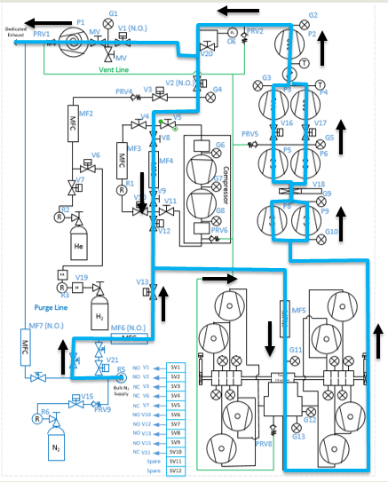
Fig. 4.14 The schematics of purge mode of operation. Image courtesy of Brandon Ewert.
- button: Click on this button once when the system is in run mode of operation (especially after and if purge mode was triggered beforehand) to allow the in-vacuum PIPS detectors to be biased.
- : In case of an emergency, this button can be pushed. After pressing this button, the system will be switched to the
purgemode and flushes the gas out of the system. It will also disable the HV card and will cut off power to the silicon detectors. It is therefore, advisable to debias these detectors before pressing the emergency stop button if time allows. To switch the system from this mode to another, click on the button and then switch to ventmode. If you do not intend to vent the system, immediately switch topumpmode.
The modes of operation of the extended gas target can be switched as follows:
From the manual mode of operation (
MAN), the system can only be switched toAutomode, where the control system becomes automatic and takes care of opening/closing various valves depending on the selected mode of operation. The action of switching toAutomode from theMANmode forces all the valves to be in their default state (the state they are in when they are not powered). Therefore, if the high vacuum pumps are ON while the system is switched toAuto, try to immediately switch to pump mode or you will run the risk of exposing the turbo pumps to nitrogen flowing into the system viaV13. The fact thatV13will be opened and nitrogen comes into the system is not an immediate danger to the turbo pumps because we have setMF6to have a flow of 1000 sccm and even if this is not the case, a needle valve upstream ofMF6(see Fig. 4.6) is also set to only allow a small flow throughMF6to avoid loading/harming the turbo pumps. It is for this reason that it is crucial to not touch that needle valve to keep the flow as is. If the high vacuum pumps are not running, one can also switch toventmode fromAutomode.From
pumpmode, one can switch toventmode,fillmode, andMANmode.From
ventmode, the system can be switched topumpmode andMANmode. If the system is inpurgeorpumpmode and the scroll pump loses power or fails, the system will automatically switch toventmode. It is crucial to enter the ReA3 vault soon after this happens to turn the high vacuum pumps OFF. However, due to the very low flow of dry nitrogen set by the needle valve upstream MF6, you do have some time before you run into the risk of harming the turbo pumps.From
fillmode, one can switch topumpmode,runmode andMANmode.From
runmode, one can switch tofillmode andMANmode only.Purgemode is only accessible via pressing the emergency stop button while in any mode of operation, or via the control software automatically and while the system is inrunmode orfillmode and some interlock(s) have been met (see Section 4.5.7).E-stop (Emergency stop:
): this is accessible from any mode of operation. Operator can initiate a purge in case of an emergency using this button.When the system is in
purgemode regardless of what causes the system to be in this mode, one has to click on the button and then switch to ventmode. If you do not intend to vent the system, immediately switch topumpmode after the system has been switched toventmode.
Fig. 4.15 and Fig. 4.16 summarize the discussions above.
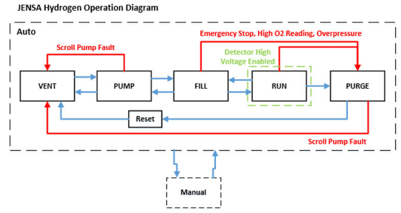
Fig. 4.15 The schematics of SECAR’s extended gas target’s operation. The blue arrows show you which modes can be switched to one another. The red arrows indicate interlocks. The rectangles are operation modes, all of which have automatic control except the manual mode of operation. The PIPS detectors can only be biased in the run mode of operation. Image courtesy of Brandon Ewert.
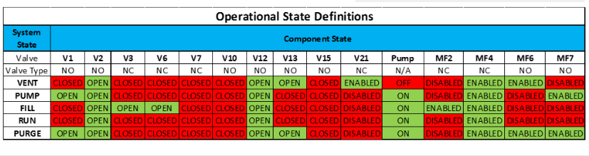
Fig. 4.16 This schematics displays all the automatically controlled devices of the SECAR’s extended gas target’s GHS. Image courtesy of Brandon Ewert.
4.3.3. Supplemental Controls
The main CAEN power supply for the two in-vacuum PIPS detectors of the extended gas target can be turned ON/OFF from the controls located in this section via the ON_CMD button. The power status of this power supply can be known by looking at the ON_RCMD readback indicator (1 or green means ON, 0 or red means OFF). The two in-vacuum PIPS detectors can only be biased when:
The reset button (
) found under operating mode controls section of the CS-Studio control page is pressed ANDIf the oxygen level is below \(0.4\%\) AND
The system is in the
runmode of operation ANDThe pressures read by the
SCR_BTS34:CMG_D1465KandSCR_BTS34:CMG_D1465Mgauges are below 25 Torr and 10 mTorr, respectively.
Only then, these detectors can be biased by first turning ON their positive HV card via the EN_CMD_POS1 button located in the “Supplemental Controls”. The EN_CMD_NEG2 to EN_CMD_NEG4 buttons located in the “Supplemental Controls” turn ON the three negative HV cards used to bias the BGO array detectors. Therefore, these cards should be turned ON before biasing the individual BGO array detectors.
For more information about the power supply, please see Section 4.8.1.
4.4. Extended Gas Target Vacuum System
This section describes how to turn ON/OFF the high vacuum pumps and the scroll pump of the extended gas target.
4.4.1. How to Turn Pumps ON
Important
Task instruction: pump down
Initial state is that the extended gas target is vented and fully closed up:
Ensure that all flanges are closed and all bolts are tightened.
Check to ensure the first beamline gate valve of SECAR (
SCR_BTS35:BGV_D1483) and the last ReA beamline gate valve (ReA_BTS34:BGV_D1450) are closed.Make sure
V4andV5are closed andV8andV9are both open. These are manual valves on the gas handling system.Make sure the scroll pump’s power switch is in OFF state (only then it will be remotely controlled). The pump will be turned ON by the control software when you switch to the
pumpmode of operation. It will be turned OFF again by the control software when you switch to theventmode of operation.Make sure the manual
AIR VENTvalve located on the scroll pump is fully closed.Make sure the
V21vent valve is closed (this valve can only be controlled usingMANmode orventmode).Make sure the intentional air leak valve and its associated MFC are closed (
SCR_BTS34:MFC_D1465G:MODE_CSET_MFCset toCLOSE, see Fig. 4.18).Close the manual valve on the roughing pump (
VROUGH).Make sure the scroll pump’s control cable, as well as all the control cables for all valves of the gas handling system are in place (see Fig. 4.19), properly connected (see Table 4.3), and secured.
Make sure mass flow meters
MF2,MF4,MF6andMF7are properly connected and the needle valves forMF6andMF7are in the locations they should be: flow rates should be 1000 sccm.
|
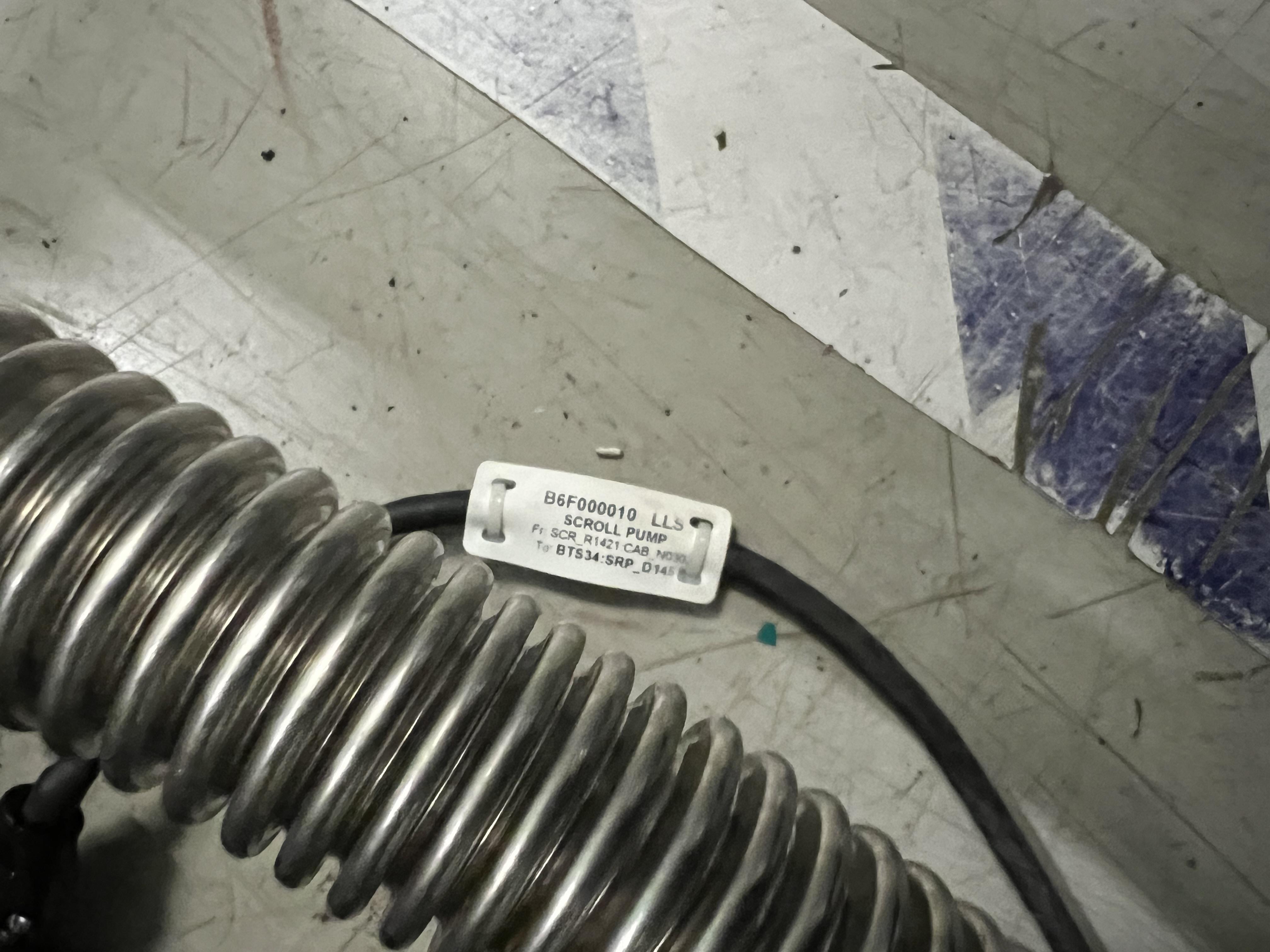
Fig. 4.17 The JENSA scroll pump should be left at the OFF state and the interlock cable should be connnected to it. Only then, it can be remotely controlled. |
Important
Task instruction: intentional air leak
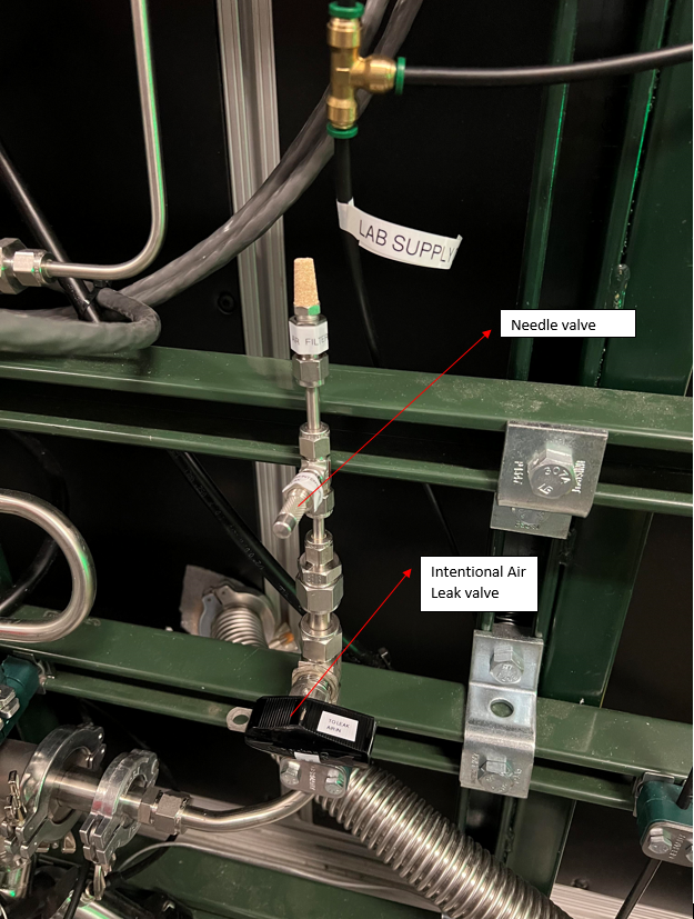
Fig. 4.18 This valve should always be closed unless one wants to test the integrity of the oxygen sensor via creating an intentional air leak, which can be done with MFC G. This MFC has a max flow of 10 sccm that can be read via probe command SCR_BTS34:MFC_D1465G:F_RD, adjusted via SCR_BTS34:MFC_D1465G:F_CSET and opened to setpoint via SCR_BTS34:MFC_D1465G:MODE_CSET_MFC set to SETPOINT, (need to update photo since the valve and MFC are now on the target side, injecting the oxygen into the low pressure target chamber). The yellow metallic cone is an air filter.
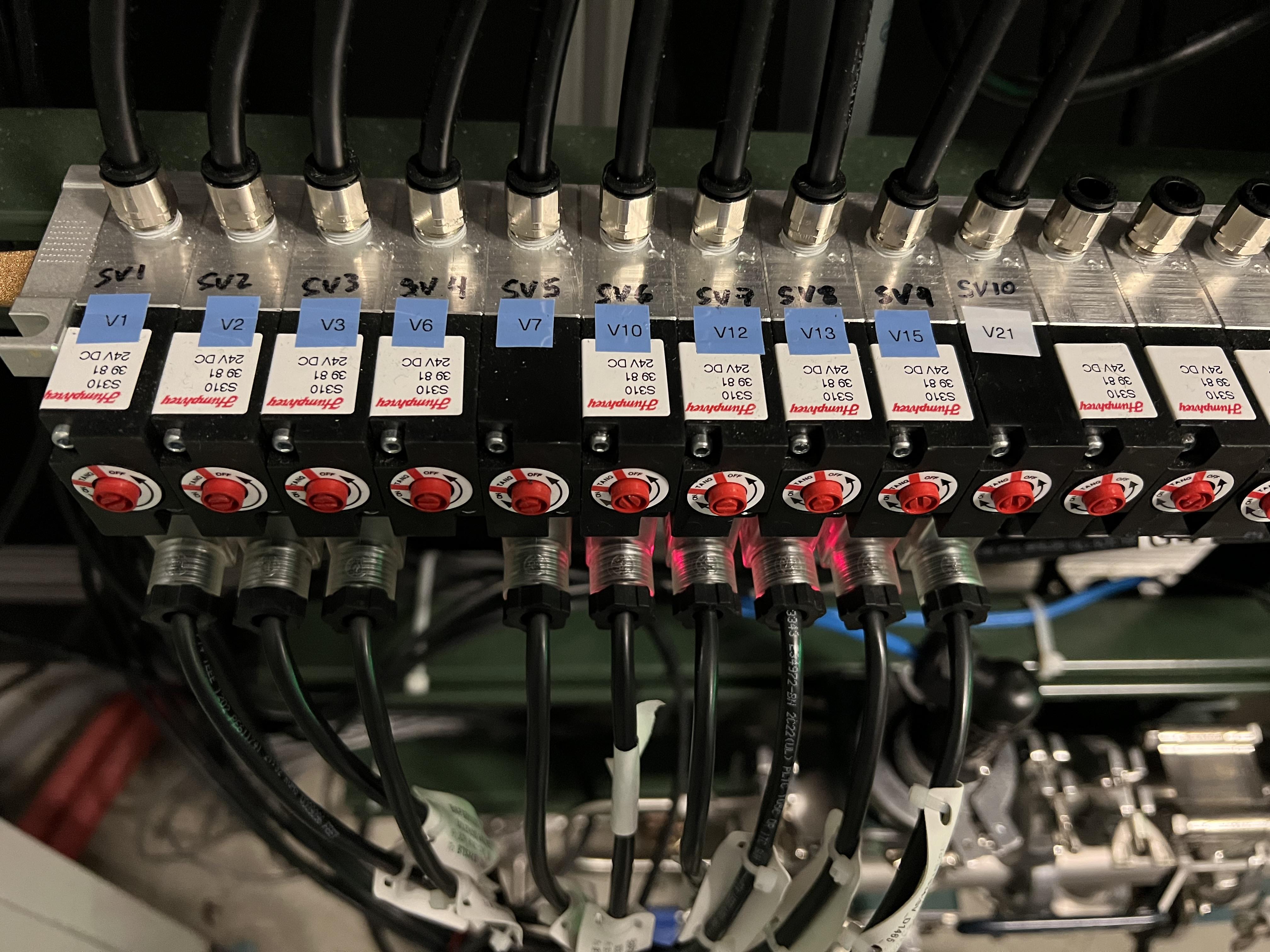
Fig. 4.19 The valves of the gas handling system need to be properly (see Table 4.3) connected to these solenoid valves before the system can be operated.
GHS Valve |
Solenoid Valve |
V1 |
SV1 |
V2 |
SV2 |
V3 |
SV3 |
V6 |
SV4 |
V7 |
SV5 |
V10 |
SV6 |
V12 |
SV7 |
V13 |
SV8 |
V15 |
SV9 |
V21 |
SV10 |
Important
If V7 is connected to SV4 and V6 is not connected to any solenoid valve, then the auto controlled valves operate the target with He. For hydrogen mode connect V7 securely to SV5 and V6 to SV4.
Make sure the water valves to the turbo pumps are all ON located on the manifold near SECAR’s first quadrupole (see Fig. 4.21). One of these valves is closed and shall remain closed as it was for the Monster turbo pump, which is not used with the extended gas target.
Turn ON main laboratory supply of water flow (see Fig. 4.22) by first turning OFF the bypass valve, then turning ON the water return valve and finally turning ON the water supply valve. The supply line has a high pressure and should be closed first and opened last.
Open the CS-Studio control page of the gas target (see Fig. 4.1).
Click on
Pumpbutton under operating mode controls found on the control page.Close the valve with black handle labelled as “To Leak Air In” (see Fig. 4.18).
Slowly open the manual valve on the scroll pump (
VROUGH) and listen carefully for large leaks and abnormal sounds. If the pump sounds normal, fully open the manual roughing valve.Check the capacitance manometers to ensure the pressure is decreasing at a good speed.
Once the pressure inside the gas target reaches 0.5 - 1 Torr:
Turn ON the DV650 screw pumps. Pump P1 is currently offline and needs repairs but is not needed for the extended gas target. Wait till P2 & P3 reach full speed (120 Hz). Make sure the pumps’ indicators are all green and are running at full speed. To turn these pumps ON, you need to go to the ReA3 high bay. Find their control panel (see Fig. 4.20).
Make sure water is flowing (one of the above-mentioned steps).
The panel is a touch panel. Touch the “GRAPHIC” on the bottom of the panel. A schematics diagram shows up, and you will see a red pump and two yellow pumps.
On top of the diagram, find “System #1 Control Panel” button and touch it.
A new window pops up. Touch “System Run”.
At this point two of the pumps turn green and start increasing their speed but one still remains red. To reset the pump that has not turned ON, immediately after touching “System Run”, touch the “Fault Reset” button (at the bottom of the page) and keep pressing it for a few seconds until the red pump also turns green and starts increasing its speed. Release the button at that point.
Wait till all three pumps reach 120 Hz (full speed). They will accelerate above 60 Hz and you will hear a different frequency after 60 Hz.
Once they reach 120 Hz, you will hear some high pitched noise and they may turn yellow momentarily and go down in frequency by a few Hz but they will ramp up and turn green soon again.
If at any point, you hear a valve going, it is because the pumps fail due to not having a good water flow. Check their water flow if they fail.
Make sure all three pumps are ON, green and are running at 120 Hz before moving on to the next step.
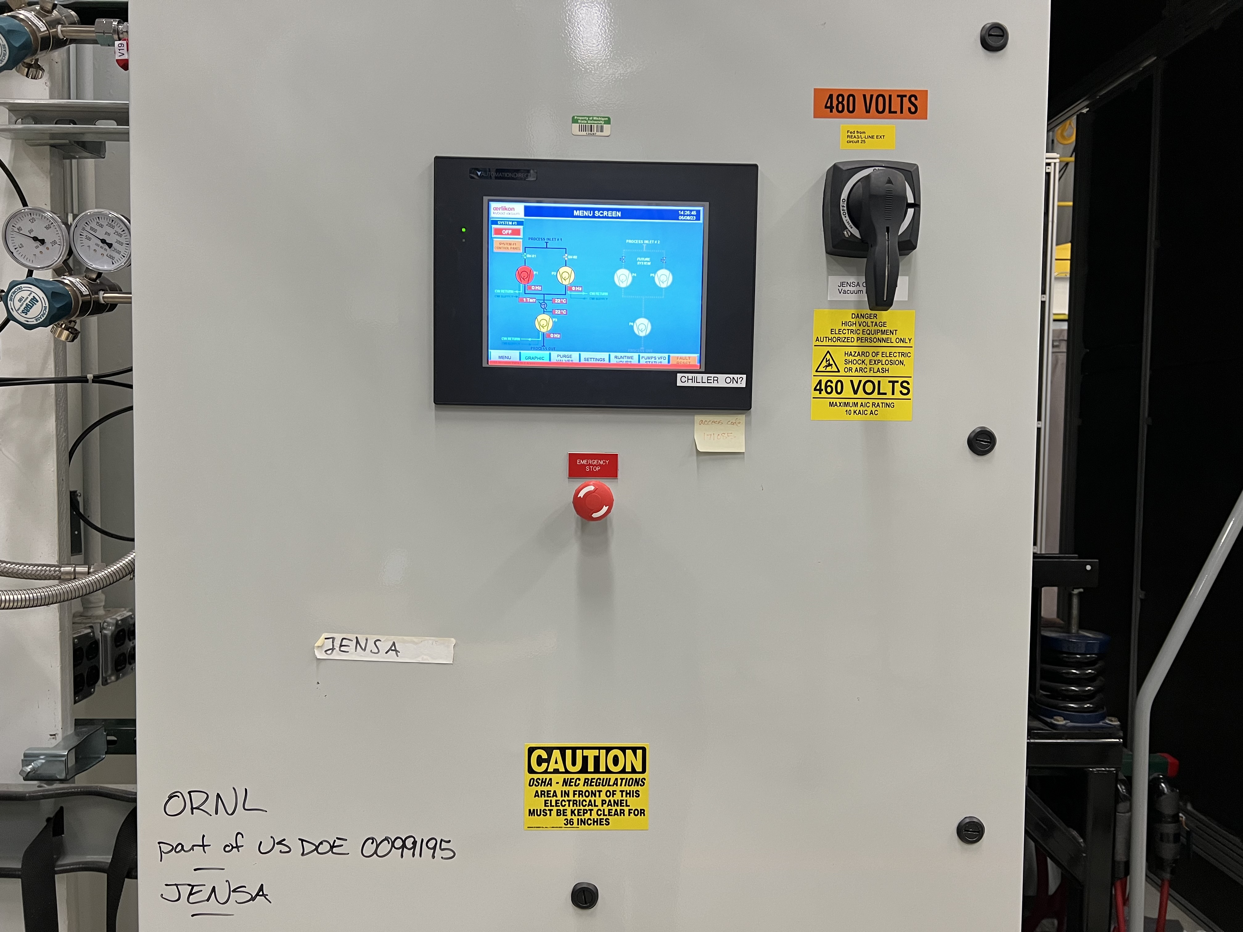
Fig. 4.20 The touchable control panel for the DV650 screw pumps.
Make sure both fans on the side of the JENSA compressor noise enclosure (see Fig. 4.23) are ON and running.
Make sure the main 208 V power for the Roots blower pumps is ON (the handle should point up, see Fig. 4.26). Turn ON the Roots blower pumps sequentially from pump 1.) to pump 6.). (Pump 7.) is disconnected for the extended gas target.) Wait 10 seconds between turning each pump ON to avoid overwhelming the circuit breaker. The first two Roots blower pumps are underneath the noise reducing enclosure around the JENSA compressor.
Turn ON the turbo pumps with the following sequence:
Upstream 1 and downstream 1. From this step onwards, wait 10 seconds between each step to avoid overwhelming the circuit breakers.
Upstream 2 and downstream 2.
Upstream 3 and downstream 3.
Upstream 4 and downstream 4.
Turn ON the 4 cold cathode gauges at upstream 3, downstream 3, upstream 4 and downstream 4. These gauges have protection circuits and will turn themselves OFF if the pressure is too high (\(>5\times10^{-4}\) Torr). For this reason the gauges closer to the target were removed, since pressure can reach \(10^{-2}\) Torr in sections 1 & 2. Instead Baratron capacitance manometer gauges with 1000 mTorr range were installed at upstream 1 (
SCR_BTS34:CMG_D1459) and downstream 1 (SCR_BTS34:CMG_D1468). The CCG may show \(10^{-11}\) Torr or read “WAIT”, both of which indicate the gauge is not ON. Wait for a while and they will turn ON. The better the vacuum, the more time it takes for them to come ON. These gauges can be read remotely via theJENSACS-Studio page, located under “SECAR Global Controls” (see Fig. 4.24).Wait till all turbos reach their full speed: their LED lights shown as load will sequentially go all the way up and come all the way down. Once at full speed, there should be no load on them and only 1 LED light should be ON. The Varian turbo pump (used as the upstream 4 pump and labelled as “Temp UP 4”) does not have any load LEDs but can display power and temperature. It should be rotating at 42k RPM when at full speed. Downstream turbo pump 4 can dispay the power and temperature as well.
The last ReA beamline gate valve has an interlock with the
SCR_BTS34:CCG_D1456gauge, which is set to \(1\times10^{-5}\) Torr. If the pressure read by this gauge is above this limit, the gate valve cannot be opened. Once the pressure reaches below the aforementioned set point, one would need to reset this PV:SCR_BTS34:CCG_D1456:VAC_RST_CMDand only then, the gate valve can be opened.The first SECAR beamline gate valve (
SCR_BTS35:BGV_D1483) has an interlock with theSCR_BTS34:CCG_D1471gauge, which is set to \(2\times10^{-5}\) Torr. If the pressure read by this gauge is above this limit, the gate valve cannot be opened. Once the pressure reaches below the aforementioned set point, one would need to reset this PV:SCR_BTS34:CCG_D1471:VAC_RST_CMDand only then, the gate valve can be opened.
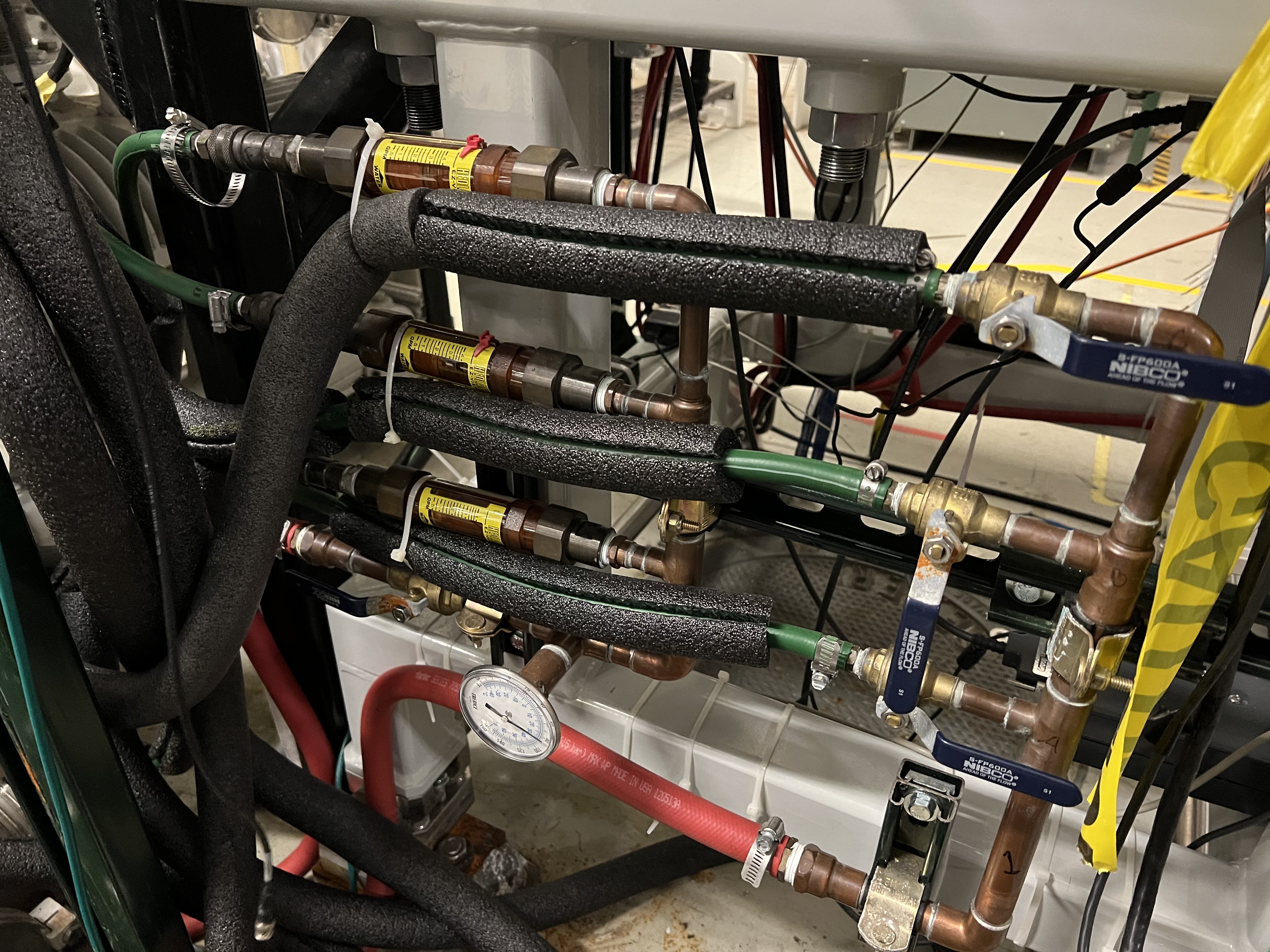
Fig. 4.21 This water manifold can be found near the first quadrupole magnet of SECAR near the ground and supplies the water to the JENSA turbo pumps. There is only one return valve with a thermometer on it. There are 3 supply valves, one of which is for the Monster turbopump and should remain closed for the extended gas target configuration.

Fig. 4.22 The main water supply lines for the JENSA turbo pumps.
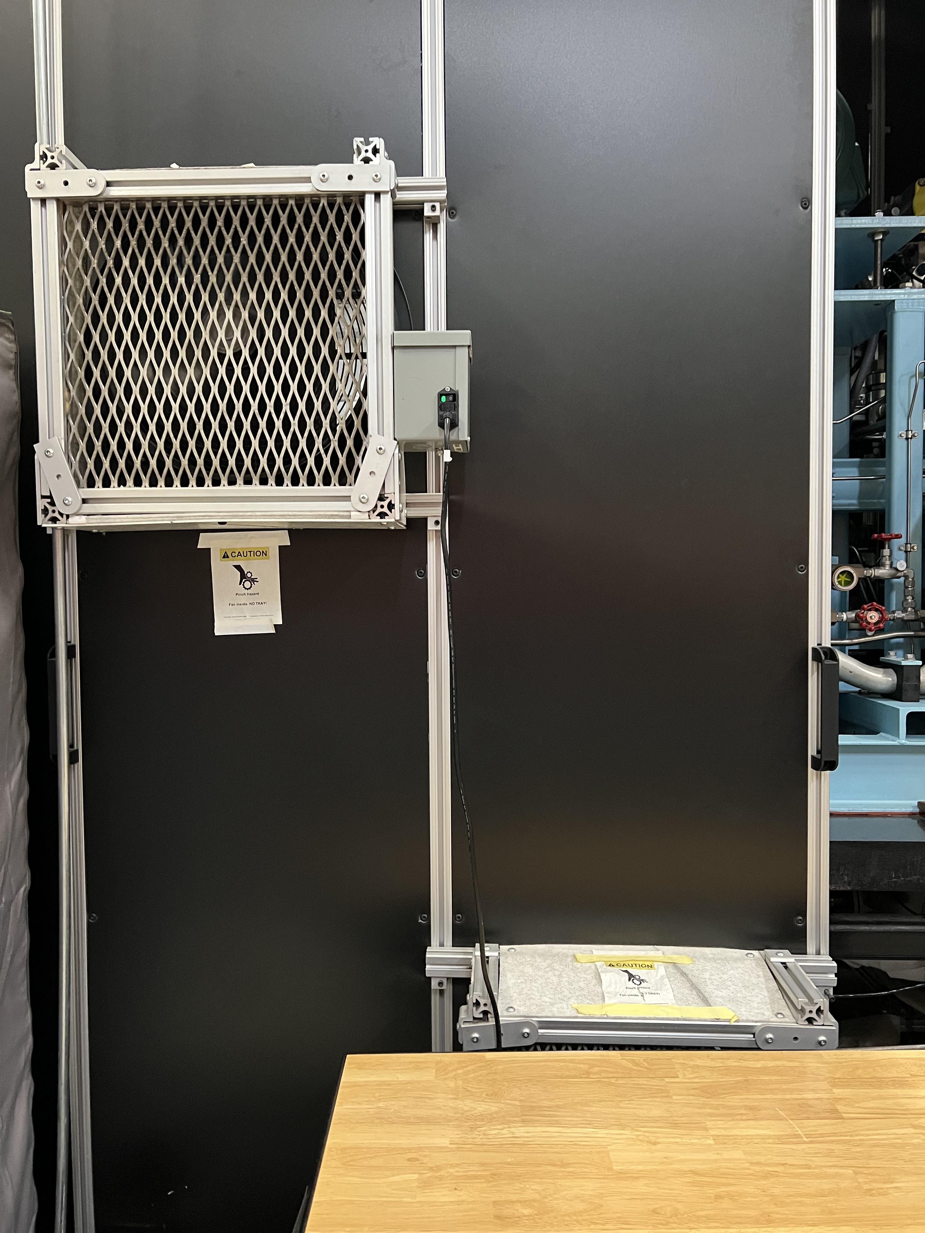
Fig. 4.23 These two fans (one hidden behind the toolbox) should be ON whenever the pumps underneath the JENSA compressor’s noise enclosure are running.
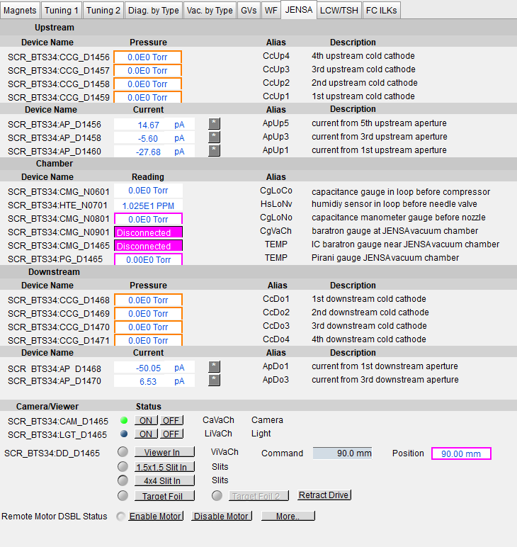
Fig. 4.24 This CS-Studio page can be used to remotely access the readback of the 8 cold cathode gauges of the gas target.
4.4.2. How to Turn Pumps OFF
This section should be executed ideally prior to venting or very soon after venting starts (which occurs either via commanding to vent by clicking on vent mode or after an emergency when the control software automatically switches to vent mode).
To turn the high vacuum pumps OFF, follow these steps:
Make sure the first SECAR beamline gate valve (
SCR_BTS35:BGV_D1483) and the last ReA beamline gate valve (ReA_BTS34:BGV_D1450) are both closed.Make sure it is safe to re-enter the ReA3 vault if the gas target was running hydrogen. If so, follow the procedure in Section 4.7.6 to re-enter the ReA3 vault.
In ReA3 high bay, find the JENSA turbo pump rack near the target area shown below (see Fig. 4.25).
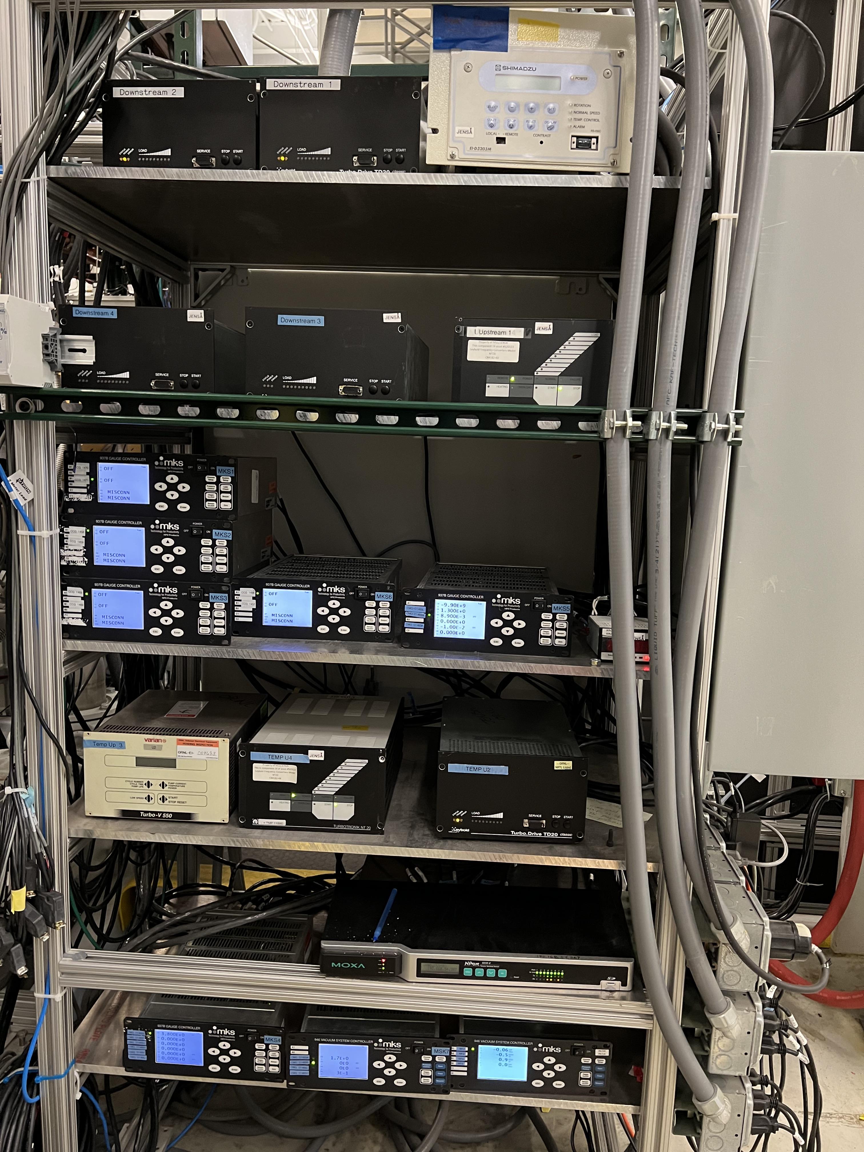
Fig. 4.25 This rack contains all the controllers for JENSA and extended gas target’s turbo pumps, cold cathode gauges, the controllers for the mass flow meters of the gas handling system, and the controllers for the capacitance manometer gauges of the gas handling system. The white controller on the top right is for the Monster turbo pump used only with the jet target.
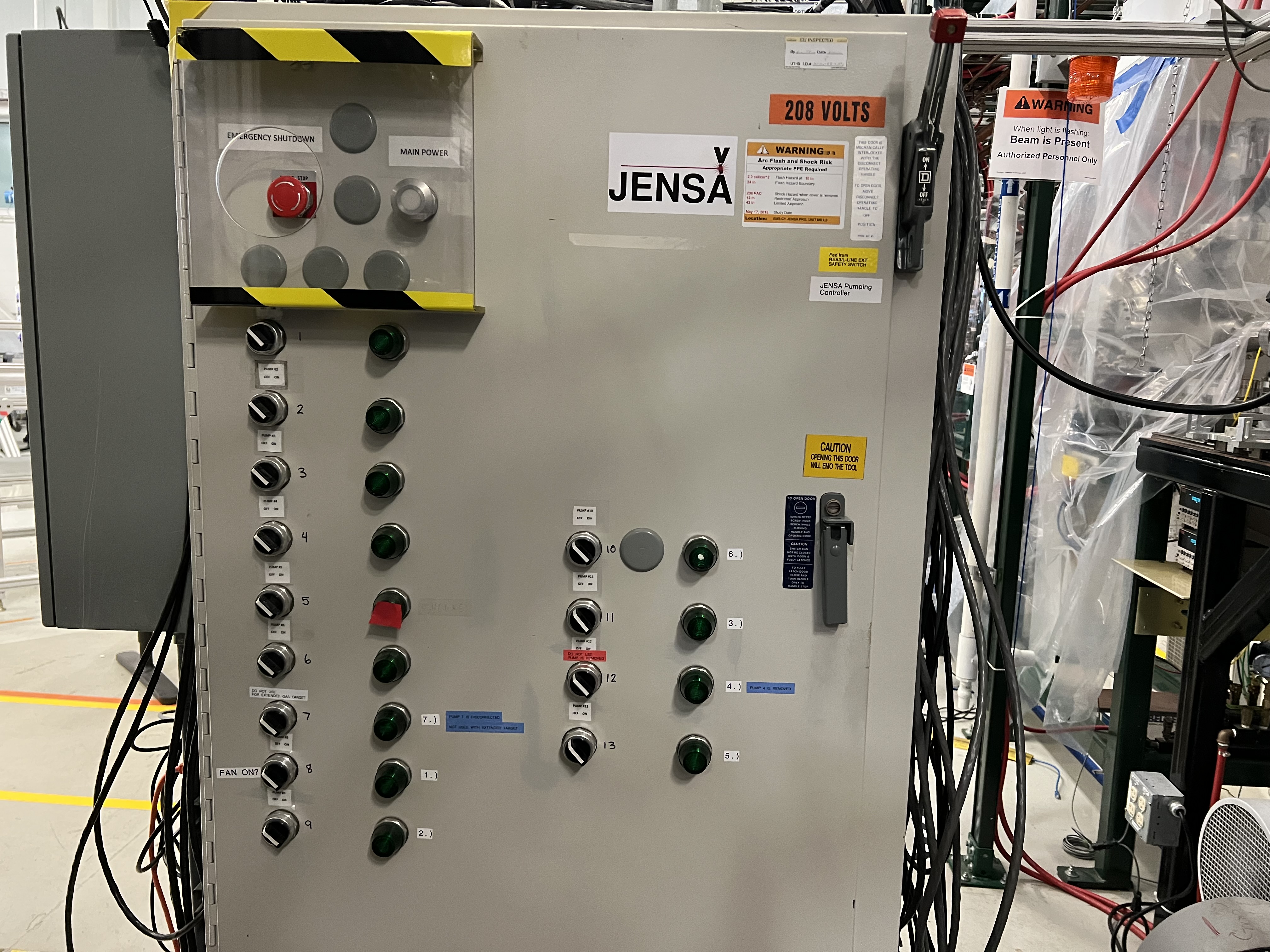
Fig. 4.26 This rack is located at the back of the rack shown in Fig. 4.25 and contains the controllers for all Roots blower pumps. The main power button on the top does not show any light when it is ON.
Turn OFF all 8 cold cathode gauges using the gauge controllers.
Turn OFF turbo pumps following the sequence below. Wait 10 seconds after each step to avoid overwhelming the circuit breaker:
Upstream 4 and downstream 4.
Upstream 3 and downstream 3.
Upstream 2 and downstream 2.
Upstream 1 and downstream 1.
Turn OFF the Roots blower pumps from pump 6 to pump 1 (i.e., in reverse order) while waiting 10 seconds after each step before switching the next pump OFF. Roots blower pump 7.) is disconnected for the extended gas target cofiguration.
Turn OFF the DV650 pumps.
Go to their control panel (see Fig. 4.20).
Touch the “GRAPHIC” on the bottom of the panel. A schematics diagram shows up, and you will see 3 green pumps running at 120 Hz.
Touch “System #1 Control Panel” button. A window pops up.
Touch “SYSTEM STOP” to stop all pumps. You will hear a valve going and one of the pumps turns red, and all of them start slowing down. The other two pumps turn yellow at some point. When they reach 0 Hz, they are fully OFF.
Close the “System #1 Control Panel” window.
Make sure all of the turbo pumps have spun down and there is no load on any of them. All LEDs except those indicating power will be OFF when the turbos have spun down all way to 0 Hz. The Varian pump (labelled as “Temp UP 3”) shows “Start pump” when the turbo pump is OFF. However, this pump keeps spinning for a long time (up to 2 hours sometimes) so to ensure it stops spinning, turn its controller’s power OFF and wait for it to spin down.
Turn OFF the main water supply lines shown in Fig. 4.22 (do not touch the small manifold near the first quadrupole magnet shown Fig. 4.21) by first closing the supply valve, then the bypass, and finally the return valve.
Turn OFF the big fan found in the walkway near the south wall facing the target chamber.
If you want to vent the system, see Section 4.5.4 if the system was running a non-explosive gas such as helium, and see Section 4.7.8 if the system was running hydrogen. Otherwise, stop here.
4.4.3. How to Zero the Capacitance Manometer Gauges
Every time the gas target needs to be operated, make sure you follow the instructions given here to zero the capaciatance manometer gauge SCR_BTS34:CMG_D1465K, which reads the pressure in the gas cell. You can do the same for all other gauges but before that, you need to ensure the pressure is lower than a threshold (indicated by the controller for each of these gauges) before you zero the gauge. Or else, you risk making the gauge inaccurate by introducing an offset in its reading.
To zero the capacitance manometer SCR_BTS34:CGM_D1465K:, which reads the gas cell pressure:
Make sure the system is under high vacuum with all pumps up and running.
Make sure the pressure is below 1 mTorr. If not, do not continue with the next steps.
Go to the pumps controller rack (see Fig. 4.25) and find the
MKS5controller unit.Using the up/down arrow buttons, select the
CMG D1465Kgauge. When this is selected, a green LED indicator will be lit beside this label.Press on the
Channel Setupbutton.Using the up/down and left/right arrow buttons, select the
Noentry (it will be highlighted blue) to the right ofManual Zero.Press
Enter. At this point the highlight color turns black.Press on the up or down button once. The
Nochanges toYes. Once this is the case, pressEnteragain to make the change.Press on the
ESCbutton.
4.5. Operation of the Extended Gas Target with a Non-Explosive Gas
When the gas target needs to be operated with a non-explosive gas such as helium, do the following:
4.5.1. Filling the pumped down system with target gas
Important
Task instruction: fill non-explosive gas
Make sure the gas target is under high vacuum (see Section 4.4.1) and that the mode of operation is set to
pumpmode.Zero the
SCR_BTS34:CMG_D1465K,SCR_BTS34:CMG_D1465MandSCR_BTS34:CMG_D1465Ecapacitance manometer gauges (Section 4.4.3) if they show an offset.Using the probe functionality in CS-Studio, verify that
MF7is CLOSED: open the probe window and search this PV:SCR_BTS34:MFC_D1465A:MODE_CSET_MFC. Then, enterCLOSEunder new value and hitEnter.MF7is used to dilute the exhaust during hydrogen operation. When the gas target is running any other gas, this mass flow meter should be closed to avoid wasting the dry nitrogen.Using the probe functionality in CS-Studio, verify that
MF2is CLOSED: open the probe window and search this PV:SCR_BTS34:MFC_D1465B:MODE_CSET_MFC. Then, enterCLOSEunder new value and hitEnter.MF2is used to control the filling rate. One should start with the closed valve to make sure the target is only filled when its ready.Using the probe functionality in CS-Studio, verify that
MF4is OPEN: open the probe window and search this PV:SCR_BTS34:MFC_D1465D:MODE_CSET_MFC. Then, enterOPENunder new value and hitEnter.Click on
MF4indicator on the CS-Studio control page. A small window pops up. Make sure the flow set point is set to fully open (flow = 500 sccm).Switch the operating mode from
pumpmode tofillmode.Click on
MF2indicator on the CS-Studio control page. A small window pops up. Set the flow to 100 sccm.Set
MF2to SETPOINT: open the probe window and search this PV:SCR_BTS34:MFC_D1465B:MODE_CSET_MFC. Then, enterSETPOINTunder new value and hitEnter.Watch the gas pressures inside the gas target and the foreline. Once the desired gas pressure inside the gas target, read by capacitance manometer G11 (
SCR_BTS34:CMG_D1465K), is reached, setMF2flow set point back to 0 sccm.Switch to
runmode of operation to recirculate the gas. To operate the detectors, see Section 10.1.Once in
runmode, setMF4to SETPOINT mode using the Probe functionality (see above)Adjust
MF4(by clicking onMF4indicator on the CS-Studio control page) set point for regulating the flow to the gas target. It is recommended to set the flow setpoint of MF4 to the actual flow readback that it is reading. This action ensures better stability of the pressure inside the gas target, as opposed to leavingMF4fully open (flow = 500 sccm).While in
runmode, if the gas pressure has to be increased, you may be able to adjustMF4and get the desired new pressure. If the desired pressure is higher than what is available in the system, the system can be switched back tofillmode until the desired pressure is reached in the gas target. In that case, before switching tofillmode:Stop the DAQ and scalers if they are running.
Debias the PIPS detectors safely (see Section 10.1).
Fully open
MF4to have a flow of 500 sccm.Then, switch to
fillmode.Open
MF2to 100 and allow the gas target’s pressure to reach the desired value.Then, set
MF2flow setpoint to 0 sccm.Finally, switch back to
runmode and readjustMF4flow to its actual readback flow.Bias the PIPS detectors again.
If the system is in
runmode, and the system has to be switched topumpmode:First make sure DAQ and scalers are stopped.
Then, the in-vacuum detectors should be safely de-biased (see Section 10.1).
Switch to
fillmode without changing the flow rate ofMF2(leave it at 0 sccm). Immediately after that, switch topumpmode.
While in
runorfillmode, carefully monitor the oxygen content indicated by the oxygen sensor readback located on the supplement controls section of the gas handling system’s control page. Make sure it does not rise. If it is rising, you have a leak in the system. Depending on how fast it is rising, you may need to interrupt the operation and either purge the system manually (see Section 4.5.2) or stop and leak check the gas target.
Warning
The system will automatically be switched to purge mode if the oxygen level in the system, detected by the oxygen sensor, reaches \(0.4\%\) while the system is in fill or run mode.
If you need to leave the system under high vacuum, switch to
pumpmode (if inrunmode, stop DAQ and turn off the in-vacuum detectors, then you need to first go tofillmode, and immediately switch topumpmode).If you need to change to
MANmode, you can do so from any operating mode. Just remember to press onAutowhen you want to switch to another mode from theMANmode. After pressing on Auto, all normally open valves will be opened. So, if the high vacuum pumps are ON:Make sure
MF6is set to 1000 sccm andV21is closed before going toAutomode.Once in
Automode, switch immediately topumpmode.If high vacuum pumps are OFF and you switch to
Automode, you can go toventmode orpumpmode from theAutomode.
To vent the system, see Section 4.5.4.
4.5.2. Purging System Manually in case of a Slow Rising Oxygen
If oxygen is rising when the system is being filled with a gas, it could be the case that the oxygen is coming into the system because of some previously trapped oxygen in the gas supply line. In that case, a thorough purging of the system helps getting rid of this trapped oxygen. To do this:
While the high vacuum pumps are ON, switch to
pumpmode (if the system is inrunmode initially, stop DAQ and turn off the in-vacuum detectors. You then have to switch tofilland then immediately switch topumpmode).Switch to the
MANmode of operation and make sure the roughing pump is ON andV1is open. Make sureV13is closed.Set the flow of
MF4to 500 sccm.Set the flow of
MF2to 100 sccm. OpenV3andV7. Let the system be filled with helium for at least 1 hour.After an hour of purging the system, set the flow of
MF2to 0 sccm. CloseV3andV7.Keep the scroll pump ON and leave
V1open and let the system run like this (pumping the gas out in non-recirculating state) for at least another 1 hour or more.These actions will hopefully flow the trapped air out of the system and may help stopping the oxygen content from rising.
4.5.3. Removing Non Explosive Target Gas and Leave System Pumped Down
If the system is in run mode:
Stop DAQ and scalers.
Safely debias the PIPS detectors.
Verify
MF6is set to 0 sccm - for non explosive gas we do not need to purge with nitrogenPress on the
button to initiate a purge.Press on the
button.Switch to
ventmode.Switch to
pumpmode.The gas will then be pumped out and the system will go to high vacuum
4.5.4. Venting the System after Running with a Non Explosive Gas
To vent the system after running the gas target with a non-explosive gas, do the following:
If the system is in
runmode when it is decided to vent the system:Stop the DAQ and scalers if they are running.
Safely shut down the in-vacuum detectors (see Section 10.1).
Ensure
MF2is set to 0 sccm. Then, switch tofillmode and immediately after switch topumpmode.
Make sure the first beamline gate valve of SECAR (
SCR_BTS35:BGV_D1483) is closed.Make sure ReA’s last beamline gate valve (
REA_BTS34:BGV_D1450) is closed.While in
pumpmode, turn all the high vacuum pumps OFF. To do so, follow all the steps in section Section 4.4.2.Proceed once you completed all steps in section Section 4.4.2.
Wait until all the turbo pumps fully spin down to zero.
Make sure all the turbo pumps have spun down. Put your hands on each of the turbo pumps and make sure you do not feel any vibration. Only then, you can safely say the turbo pumps are OFF.
You can now have the option to vent with air or with dry nitrogen. The latter is a safer option because it keeps the system dry and dust free.
To quickly vent the system with air (this action should only be allowed if the system has not been operated with hydrogen recently):
Switch to
MANmode of operation.Close the manual roughing valve (
VROUGH) on the scroll pump.Open the manual
Air Ventvalve (see Fig. 4.27) on the scroll pump slowly. Once the pressure gauges in the gas handling system read 730 – 760 Torr, the system is vented. Note thatSCR_BTS34:CMG_D1465KandSCR_BTS34:CMG_D1465Mwill only read 100 Torr and 1 Torr, respectively, since these are the maximum pressures reached by these two gauges.
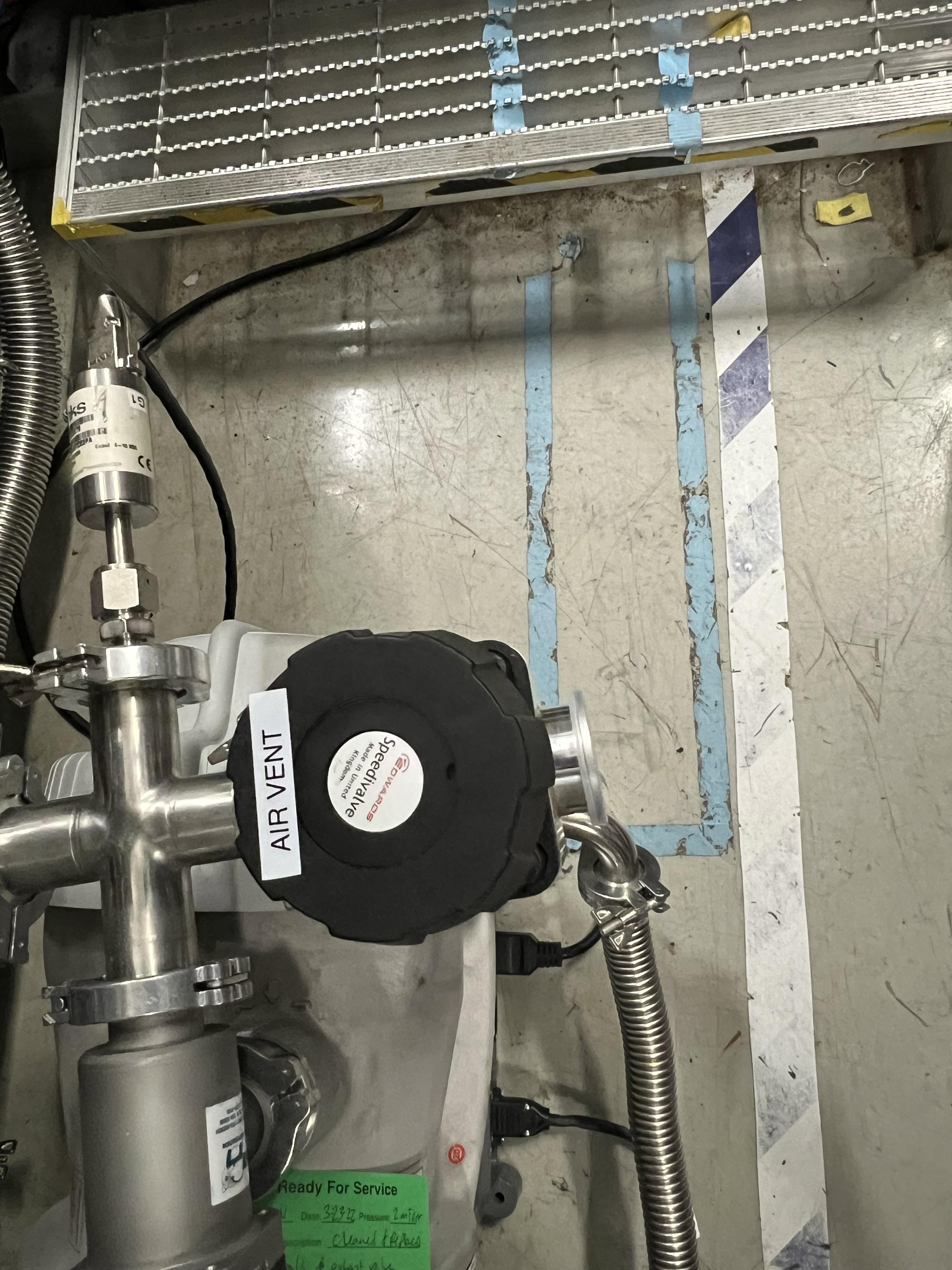
Fig. 4.27 This vent valve attached to the JENSA scroll pump vents the system with air without any filteration.
To vent with dry nitrogen:
Open the CS-Studio control page of the gas target (see Fig. 4.1).
Using the probe feature of CS-Studio, make sure
MF4is open:SCR_BTS34:MFC_D1465D:MODE_CSET_MFCshould haveOPENin its “Value”. If “Value” isCLOSE, enterOPENunder “New Value” and hitEnter. Make sure Value changes toOPEN.Using the probe feature of CS-Studio, make sure
MF6is also open:SCR_BTS34:MFC_D1465F:MODE_CSET_MFCshould haveOPENin its “Value”.Set
MF6to 10000 sccm.Switch to
ventmode of operation. This will turn the scroll pump OFF.Check the nitrogen regulator of the lab nitrogen supply line shown in Fig. 4.28 and make sure it is locked on 5 psi.
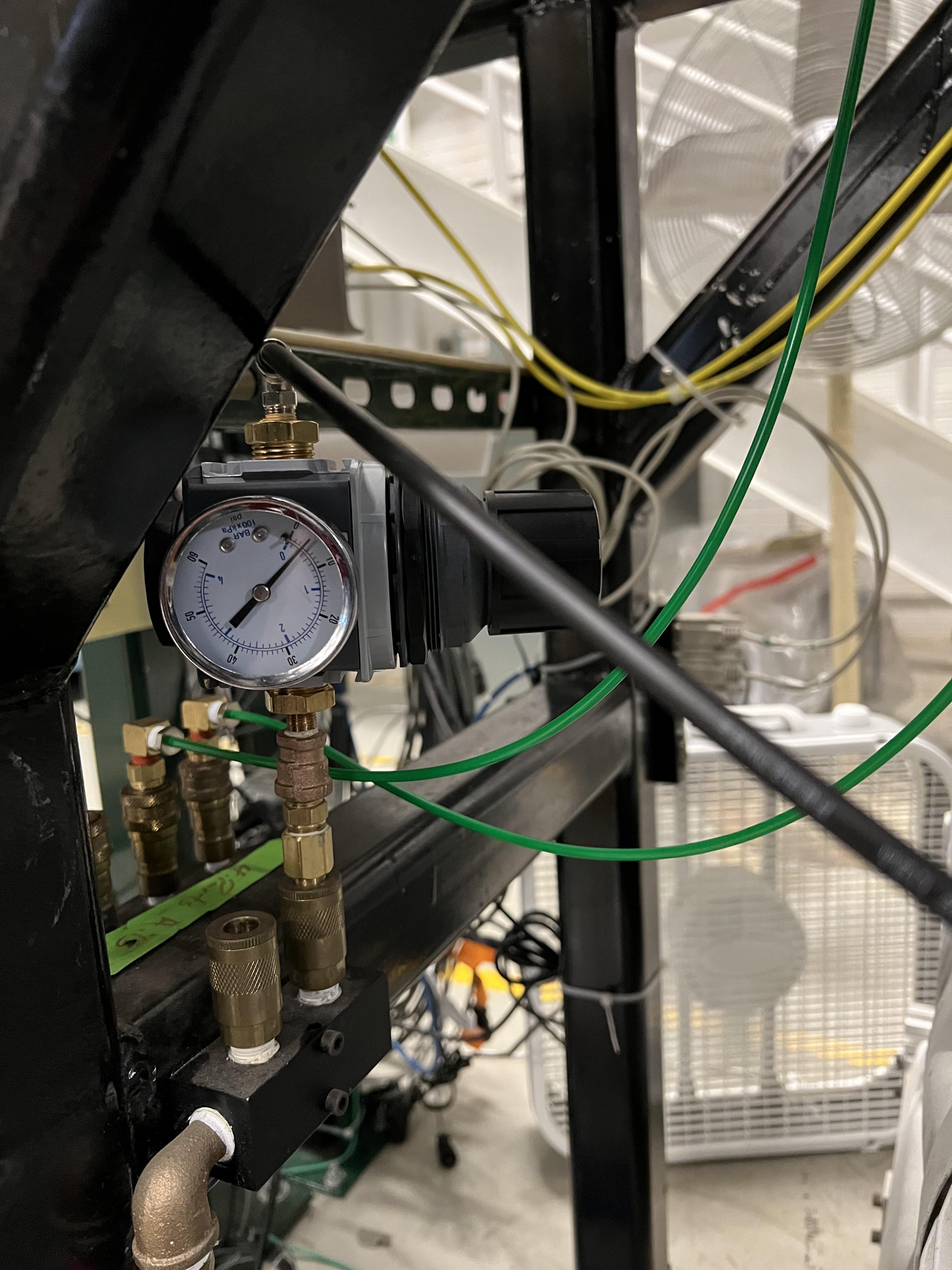
Fig. 4.28 This regulator, located below the SECAR Keithley modules, is locked to flow 5 psi of dry nitrogen from the laboratory nitrogen supply line into the SECAR’s gas handling system for the targets.
Open
V21by clicking on theobutton underneath the valve on the CS-Studio control page.Monitor the pressure gauges. If they are coming up too slowly, open the metallic needle valve shown in Fig. 4.29 all the way. If the system is venting too quickly, reduce the flow rate of
MF6to 5000 sccm and/or adjust the metallic needle valve shown in Fig. 4.29. Please avoid changing the regulator to speed up venting process or else you need to change it back to where it was to have a safe flow of dry nitrogen for purging. Once the pressure gauges read 730 – 760 Torr, the system is fully vented. Note thatSCR_BTS34:CMG_D1465KandSCR_BTS34:CMG_D1465Mwill only read 100 Torr and 1 Torr, respectively, because these gauges reach a maximum of 100 Torr and 1 Torr, respectively. With the nitrogen regulator locked at 5 psi, the dry nitrogen flow rate throughMF6is about 7.4 standard liters per minute. The total volume of the system is about 421 liters so it takes a bit more than 1 hour to vent the system.Close
V21and its needle valve (see Fig. 4.29).

Fig. 4.29 This needle valve, labelled “For Vent” should only be opened when one wants to speed up the venting (with dry nitrogen) process by openning V21 valve, which can only be opened if the system is in MAN or vent mode of operation. Please close the needle valve when the system is fully vented.
Set
MF6flow rate to 1000 sccm to make it safe again for purging in case the system switches topurgemode automatically the next time the system is running.Switch to
MANmode of operation and closeV13valve.Close the manual valve (
VROUGH) on the roughing pump.If the system has to be opened to air (for example, something in the chamber needs to be taken off the beamline) or if the system is not going to be used for a long time, close
MF6viaSCR_BTS34:MFC_D1465F:MODE_CSET_MFCPV name that can be accessed using probe functionality of CS-Studio: under “New Value”, sendCLOSEcommand and verify that “Value” \(=\)OPENchanges to “Value” \(=\)CLOSE.If you have to open the gas target’s chamber:
Please ware gloves.
Please clean the gloves with rubbing alcohol.
Using alcohol or acetone and lint free Kim wipes, please clean all sealing surfaces, o-rings and all other surfaces that are to be inserted into the vacuum chamber.
Please try to avoid using vacuum incompatible material.
If required to use tools, please clean them before using them on or around the vacuum chamber.
Please try to limit the time of exposure of the vacuum chamber to air.
Please close all flanges properly if the chamber has to be vented for an extended period of time to avoid accumulation of dust and moisture.
When you are ready to close the system and pump down, use Apiezon L or M grease on the o-rings.
If for some weird reason, vent mode has some issue and you cannot use it, venting the system can be achieved using the MAN mode of operation. To do this:
Set
MF4toOPENand a flow setpoint of 500 sccm.Set
MF6toOPENand a flow setpoint of 10000 sccm.Switch to
MANmode of operation.Close the manual roughing valve (
VROUGH) on the JENSA scroll pump.Check the nitrogen regulator of the lab nitrogen supply line shown in Fig. 4.28 and make sure it is locked on 5 psi.
Open
V21by clicking on theobutton underneath the valve on the CS-Studio control page.Open the metallic needle valve shown in Fig. 4.29 all the way. If the system is venting too quickly, reduce the flow rate of
MF6to 5000 sccm and/or adjust the metallic needle valve shown in Fig. 4.29. Please avoid changing the regulator to speed up venting process or else you need to change it back to where it was to have a safe flow of dry nitrogen for purging. Once the pressure gauges read 730 – 760 Torr, the system is fully vented.Close
V21and its needle valve (see Fig. 4.29).Set
MF6flow rate to 1000 sccm to make it safe again for purging in case the system switches topurgemode automatically the next time the system is running.Close
V13valve.If the system has to be opened to air (for example, something in the chamber needs to be taken off the beamline) or if the system is not going to be used for a long time, close
MF6viaSCR_BTS34:MFC_D1465F:MODE_CSET_MFCPV name that can be access using probe functionality of CS-Studio: under “New Value”, sendCLOSEcommand and verify that “Value” \(=\)OPENchanges to “Value” \(=\)CLOSE.
4.5.5. Emergency Shutdown Procedure for Non-Explosive Gas
see Emergency Response Procedure for SECAR Extended and Jet Gas Targets During Helium Operation.
4.5.6. How to Change the Non-Explosive Gas Bottle
Important
Task instruction: change non-explosive gas bottle
If at any time, the non-explosive gas bottle runs out of the supply gas and needs to be changed, follow the procedure below:
If the system is running with a non-explosive gas and the system is in
runmode when the gas bottle runs out of the supplied gas:Stop the DAQ and scalers if they are running.
Safely de-bias the in-vacuum silicon detectors (see Section 10.1).
Switch to
pumpmode and pump on the system for at least 15 minutes.Verify
V7,V6andV3are closed.Make sure the pressure gauges in the system read good vacuum (\(< 1\) Torr) in the system. Note that
SCR_BTS34:CMG_D1465Mshould read below 20 mTorr.Enter ReA3 vault.
Make sure you already have a cart to move gas bottles with, and you have snoop (a soapy mixture) ready.
Make sure you have a new full gas bottle on the cart.
Once in the vault, switch to the maintenance operation mode (
MANmode).Verify
V1is open and the scroll pump is ON and all high vacuum pumps are still running.Close the small metallic valve after the non-explosive gas regulator (see Fig. 4.30).
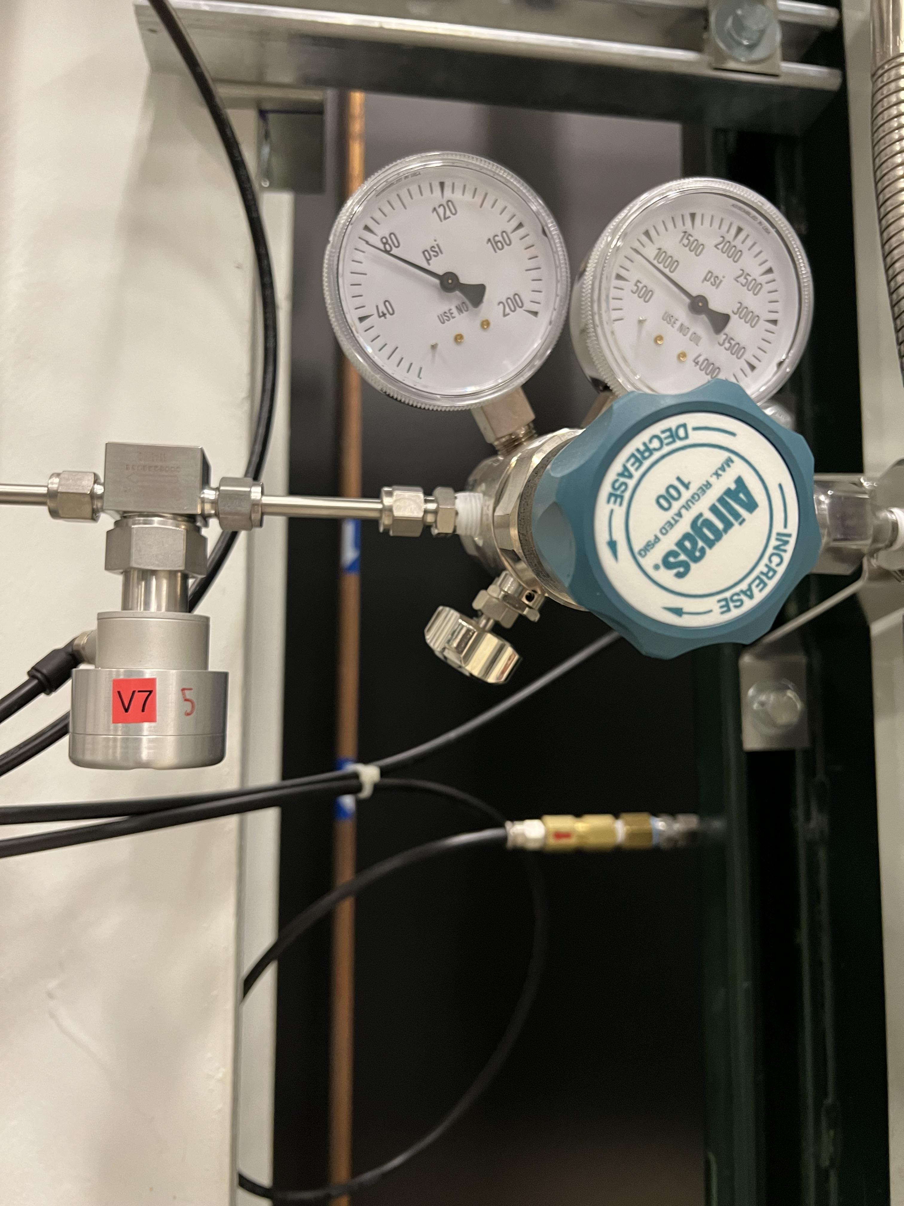
Fig. 4.30 Close the small mettalic valve attached to the regulator of the helium bottle before changing the gas bottle.
Disconnect the gas bottle from the GHS.
Remove the empty non-explosive gas bottle and move the full new gas bottle into its place.
Secure the new gas bottle by the belt which was around the empty gas bottle.
Connect the new gas bottle to the GHS pipes and tighten the pipe fittings.
Once the bottle is fully and securely attached to the GHS, open the main bottle’s valve.
Open the small metallic manual valve passed the regulator upstream of valve
V7(see Fig. 4.30).Pour snoop on the new gas bottle’s top area and the pipe fittings you just tightened and verify no bubbles are coming out.
Make sure the bottle’s regulator is set to 40 psi.
Ask the OIC to perform sweep and lock of ReA3 high bay.
Once you are back to the DataU, access the CS-Studio control page.
Switch to
Automode, and immediately without any delay switch topumpmode.Manually purge the system with the gas whose bottle was changed to remove any air bobbles. To do this, follow the procedure provided in Section 4.5.2.
Purge for at least 10 – 15 minutes.
Switch to
ventmode and then immediately switch topumpmode, and pump for at least another 15 minutes.Fill the system again with the desired gas to the desired pressure, and then switch to
runmode and carry out the rest of the experiment.
4.5.7. Trouble Shooting
If the GHS is unresponsive or multiple modes are indicated, for example, in case you forgot the reset after emergency stop the system can be recovered by:
Switch to manual mode
Set by hand all valves to an appropriate mode configuration
Switch to Auto mode
4.6. Interlocks and Alarms of the Extended Gas Target
Interlocks and alarms that are put in place for operation of the extended gas target are summarized below. Almost all of these interlocks are related to hydrogen operation but all these interlocks occur regardless of which gas is in use.
4.6.1. Interlocks:
The current interlocks are referenced in the DCC document `N3010221-RC-008874<https://portal.frib.msu.edu/sites/dcc/pages/dcclink.aspx?WBS=N3010221&Sub=RC&SN=008874>`_
In the following the triggered event, and the conditions to trigger it are summarized for each interlock. The set points are set through the MKS controllers of the respective gauges. Interlock settings can be read off the MKS controllers by selecting the channel of interest using Channel Setup (see Fig. Fig. 4.39 for an example display).
Each channel can trigger 2 interlocks indicated at the bottom of the screen. A pressure maximum is implemented as “ENABLE” below a maximum pressure. Unused interlocks are sending a CLEAR.
Vent mode triggered in
purgeorpumpmodes if:Scroll pump off. For hydrogen operation it is critical that hydrogen can be removed when needed. This is usually done in the purge or pump modes. If the scroll pump fails, the vent mode will dilute the target gas with nitrogen, and eventually push gas into the exhaust via the overpressure valves. Once the hydrogen is removed the operators need to address the root cause of the scroll pump failure, and then click on the
button found under operating mode controls of the control page before the control software allows switching to another mode of operation.
Purge mode triggered during
fillorrunmodes if:Oxygen \(>0.4\%\). This setpoint value is required to operate with hydrogen. Dry nitrogen is used to flush the system with capability to drive hydrogen out and to reduce hydrogen content in the system to low explosive levels. This triggers automatic removal of hydrogen in the event of a leak to atmosphere. The operators have to remember to click on the
button found under operating mode controls of the control page before the control software allows switching to another mode of operation. From the purgemode, you can only switch toventmode. If the high vacuum pumps are ON and you do not intend to vent the system, after the system is switched toventmode, immediately switch topumpmode.Target pressure exceeds setpoint. Target pressure is read by capacitance manometer G11 (
SCR_BTS34:CMG_D1465K). This setpoint should be adjusted to experiment requirements to be above planned max operating pressure to ensure there is no unexpected pressure increase that may indicate a leak to atmosphere or some other malfunction.Foreline pressure exceeds 500 Torr. The foreline pressure is read by capacitance manometer G2 (
SCR_BTS34:CMG_D1465B). This setpoint is required for hydrogen operation and ensures the amount of target gas is within the envelope for hydrogen operation.Additional system pressures exceed setpoints. These interlocks provide additional safeguards against leaks to atmosphere or other malfunctions. Setpoints can be adjusted as needed to be above the operating values for a particular experiment. The interlocks are:
G3 (
SCR_BTS34:CMG_D1465C) > 50 Torr. This is the inlet pressure of the last DV650 pump.G5 (
SCR_BTS34:CMG_D1465E) > 20 Torr. This is the pressure at the DV650 stage inlet/Roots blower stage exit.G9 (
SCR_BTS34:CMG_D1465I) > 10 Torr. This is the pressure inbetween the Roots blower stages.G10 (:code:`SCR_BTS34:CMG_D1465J) > 10 Torr. This is the Roots blower stage inlet pressure.
Positive HV card is disabled in
fillorrunmodes if: (The positive HV supply card used for the in-gas detectors will be disabled and voltages from all the channels of this card are reduced to 0V with a ramp down rate of \(=\) 50 V/s. The negative polarity cards used for the BGO array are unaffected.)Oxygen \(>0.4\%\). This setpoint value is required to operate with hydrogen.
Target cell pressure exceeds set point (see above) Target pressure is read by capacitance manometer G11 (
SCR_BTS34:CMG_D1465K). This setpoint should be adjusted to experiment requirements to be above planned max operating pressure to ensure there is no unexpected pressure increase that may indicate a leak to atmosphere or some other malfunction.Target chamber pressure exeeds 0.5 Torr. This is measured by G13 (
SCR_BTS34:CMG_D1465M)
Open V15 for reserve nitrogen bottle in
ventorpurgemodes if:MF6 nitrogen flow :math:`<,70%` of setpoint after 10 seconds. This ensures a constant source of dry nitrogen to vent or purge the system in case of a failure of the lab nitrogen supply system.
Enable opening of code:`V21` valve by operator
if system is in :code:`vent` or :code:`MAN` modes of operation. Only in these two modes of operation,
V21control is enabled and it can be opened by the operator if she/he desires to vent the system faster. This ensures the system can only be vented to atmosphere after purging the hydroge out of the system.
4.6.2. Alarms
Alarms are specified in the Alarm Change Request system under “Overpressure alarms for JENSA Target GHS” - for example request `ACR23-224<https://portal.frib.msu.edu/sites/engineering/Lists/Alarm%20Change%20Request/Item/displayifs.aspx?List=491f79dc-271a-4918-a164-7f85fbc1dfda&ID=270&Source=https%3a//portal.frib.msu.edu/sites/engineering/Lists/Alarm%2520Change%2520Request/AllRequests.aspx%23InplviewHash267afa80-5559-4303-9e5a-d7031424550a%3D&ContentTypeId=0x0100D709E523E131A14B9A5CE9D80DA591E7>`_
A voice alarm will be triggered in the FRIB control room if the oxygen level in the system reaches \(0.4\%\).
A standard Phoebus alarm will be triggered if the oxygen level in the system reaches \(0.1\%\).
[Add list of Alarms and instructions for setting values] [Add description of what happens when an alarim is triggered - red edge around displayed value in GHS; when is controlroom voice alarm enabled? procedure?]
4.7. Operation of the Extended Gas Target with Hydrogen
This section describes the specifics of the extended gas target while it is operated with hydrogen.
Warning
Hydrogen can be highly explosive and dangerous. Only specially trained personnel as documented in the FRIB training database can perform any role related to hydrogen operation. If you are not trained you cannot do anything described in this section.
4.7.1. Basic Featuers and Roles of Hydrogen Operation
All documents describing hydrogen operation can be found under the link JENSA Hydrogen Operating Information on the SECAR Portal homepage.
When operating with hydrogen
The system is brought into the configuraton appropriate for hydrogen operation via a configuration change request and remains in this configuration until it is changed back.
Only trained personnel can operate the gas target while in hydrogen operation mode INCLUDING ANY OPERATION WITH HELIUM
Access to JENSA controls is limited to authorized personnel based on login. Authorized personnel for hydrogen operation cannot leave control screens unattended.
There is no access to the ReA3 vault while the target runs hydrogen gas and all operation, including filling, running, and removing gas, is performed remotely. Access card readers are locked. There is a search and evict procedure prior to starting up, and a re-entry procedure for putting the system back into a safe, hydrogen free state and re-open access to the ReA3 vault.
Operation is limited to at most 13 standard liters of hydrogen, as enforced by the 430 Torr limit and interlock on capacitance manometer G2 (
SCR_BTS34:CMG_D1465B)
There are three roles as described in the SECAR Gas Target Procedure for Operation with Hydrogen
Hydrogen Lead Operator: anyone with the training “JENSA Hydrogen Lead Operator” in the FRIB training database.
Only person to start up hydrogen operation at the beginning of an experiment
Only person to change hydrogen bottle
Can perform all functions
Hydrogen User: anyone with the training “JENSA Hydrogen User” can serve as hydrogen user on shift.
Can watch proper operation of the target as directed by HUIC
Alerts HUIC if there are any problems and responds to time critical emergencies by pumping or purging the target.
Hydrogen User in Charge (HUIC): Has “JENSA Hydrogen User Training” AND is specifically designated to serve as HUIC for a specific shift by the hydrogen lead operator. The designation has to be documented in the ELOG.
In charge of watching proper running of hydrogen target and responding to any abnormal events
Can delegate watching the target to another hydrogen user temporarily
Can stop hydrogen operation temporarily, carry out the ReA3 vault re-entry procedure, put the ReA3 vault in a safe state for personnel to access it, can carry out the ReA3 vault search and evict procedure, and can restart hydrogen operation.
Documents any abnormal events
Documents and reports to the FRIB OIC successful completion of any instance of the search and evict or re-entry procedure
4.7.2. Hardware Specific to Hydrogen Operation
Two flammable gas detectors (see Fig. 4.31) calibrated for hydrogen are installed near the gas target’s GHS and inside the JENSA compressor noise reducing enclosure. They detect hydrogen leak from the gas bottle (or the high pressure line) to air.
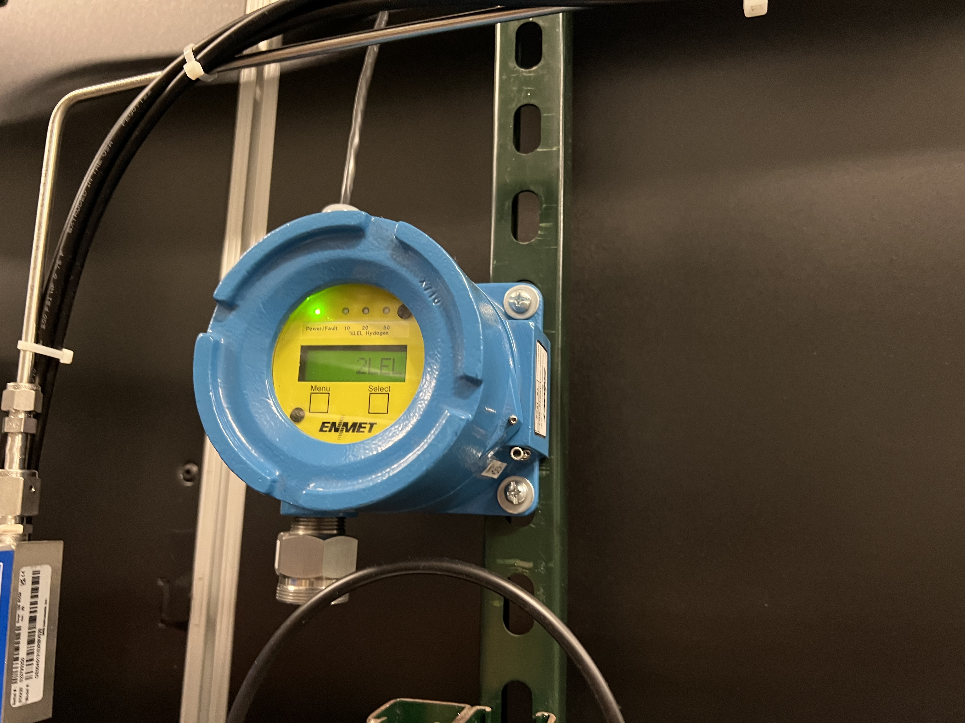
Fig. 4.31 There are two flammable gas detectors installed near SECAR’s gas target: one is installed on the gas handling system, and one is installed inside the noise reducing enclosure around the JENSA compressor. If these detectors detect hydrogen, an alarm will go off inside the ReA3 vault, which is controlled by the device shown in Fig. 4.32.
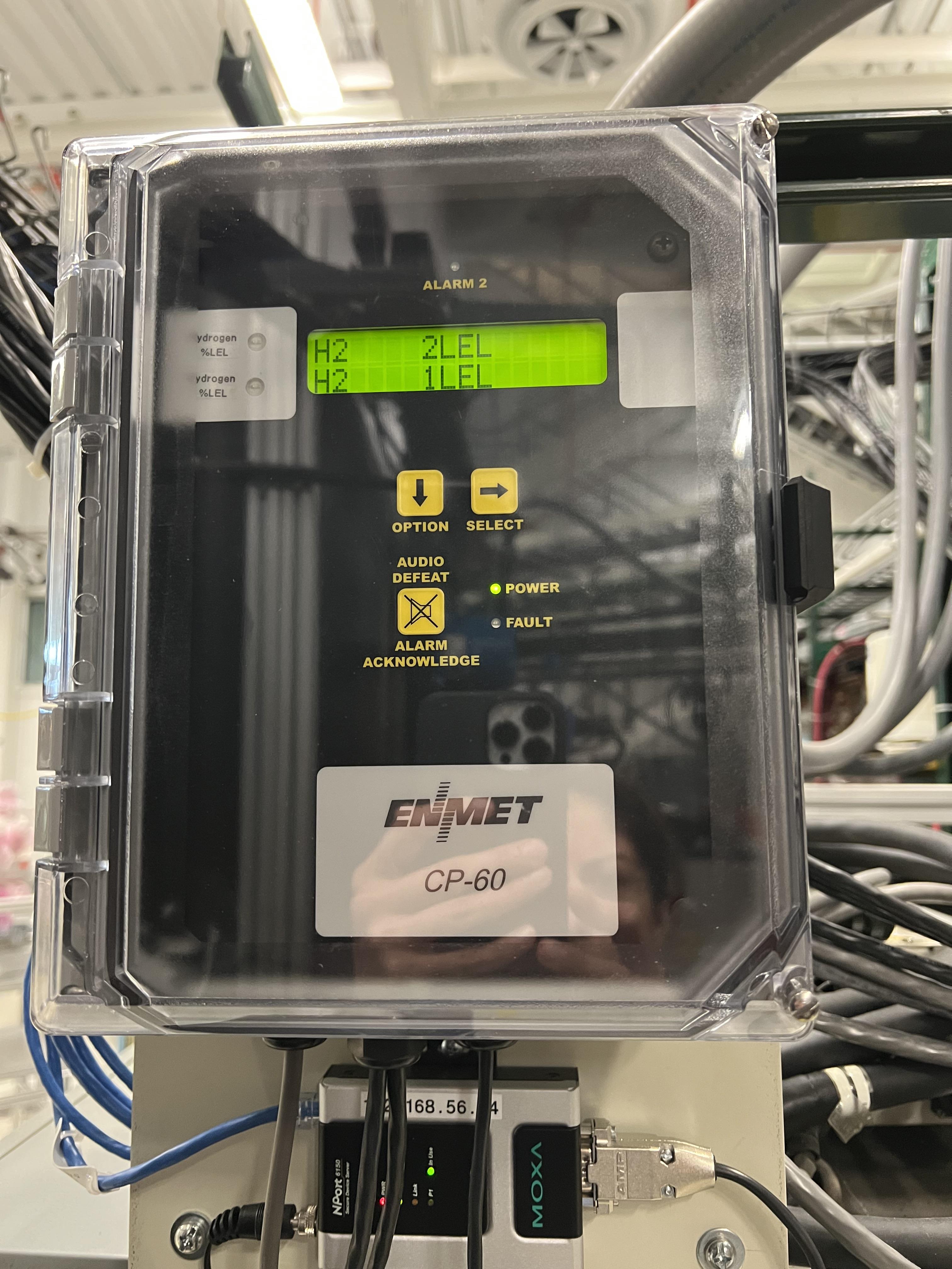
Fig. 4.32 If hydrogen is leaking into the air in ReA3 high bay, this device will sound an alarm inside the ReA3 vault. It is attached to the top of the panel that controls the Roots blower pumps. There will also be a voice alarm in the FRIB control room and operators will contact the experimenters.
There is a dry nitrogen bottle that acts as a backup in case of a failure of the laboratory dry nitrogen supply. This bottle is installed behind the touch panel for control of the DV650 pumps. Make sure its regulator is set to 15 psi at all times. If the system is in
ventorpurgemode, andMF6flow rate reads \(<\,70\%\) of its set value,V15valve will be automatically opened after 10 seconds to ensure constant source of dry nitrogen by opening the valve to the reserved dry nitrogen bottle.V15is the only valve in the GHS that cannot be commanded manually even via using theMANmode of operation.A flash arrestor (see Fig. 4.33) is installed on the hydrogen bottle to extinguish the flames and prevent the bottle from explosion.
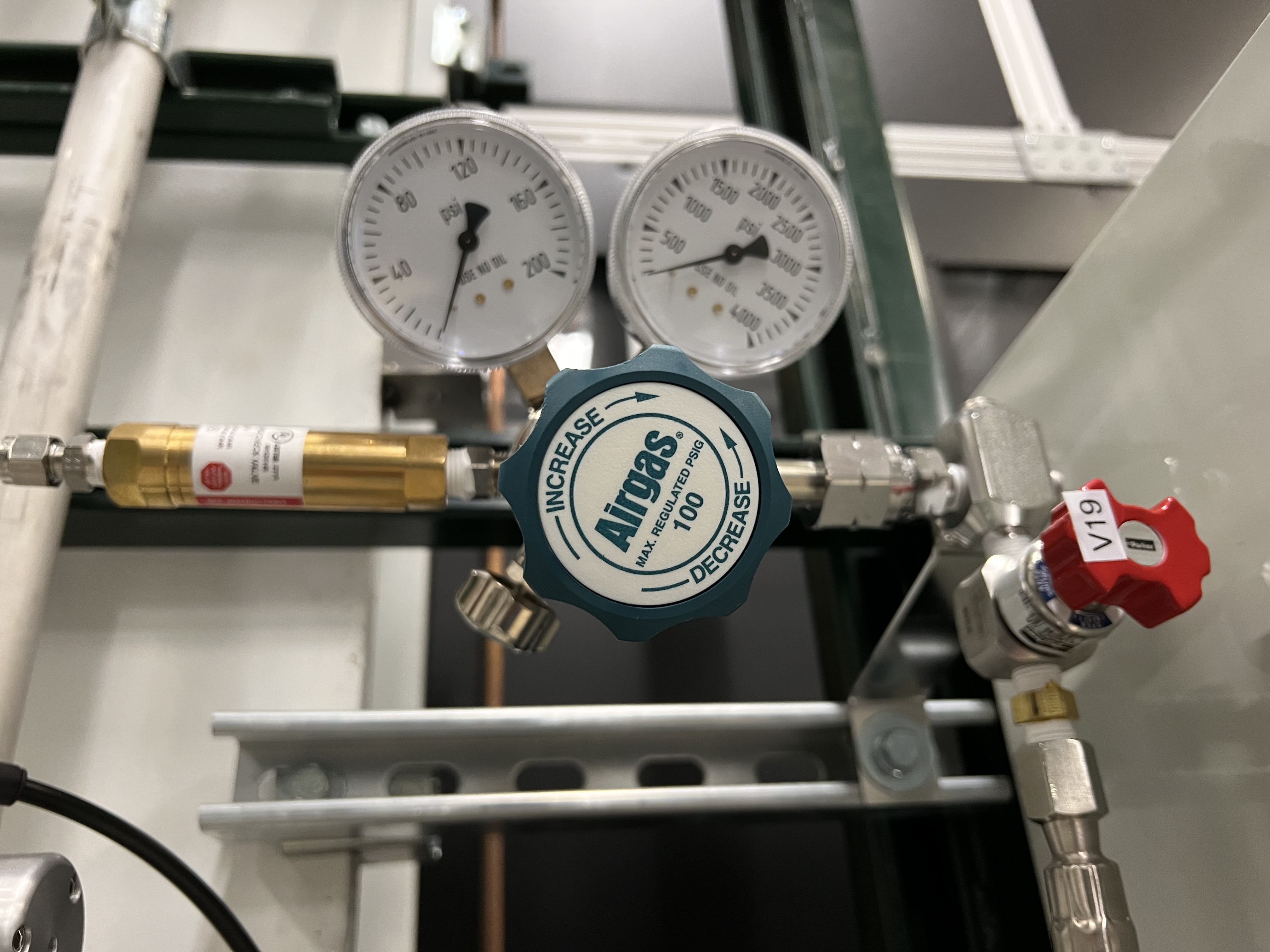
Fig. 4.33 The flash arrestor is the golden device that is attached to the hydrogen regulator.
Flow switches will be added in future to the fans in the noise enclosure of JENSA compressor. These are not installed yet and will only be installed if the JENSA compressor gets the approval to run hydrogen.
An in situ Oxygen sensor inside the vacuum system (see Fig. 4.34) allows early detection of oxygen ingress at \(< 1\%\) and \(10\%\) of hydrogen Low Explosive Level (LEL). At \(1\%\) of LEL (sensor readback \(= 0.04\%\)), a standard Pheobus alarm will be triggered. At \(10\%\) of LEL (sensor readback \(= 0.4\%\)) the system will automatically be switched to
purgemode.
Fig. 4.34 The oxygen sensor is attached to the gas handling system near the scroll pump. Its controller is shown in Fig. 4.35.
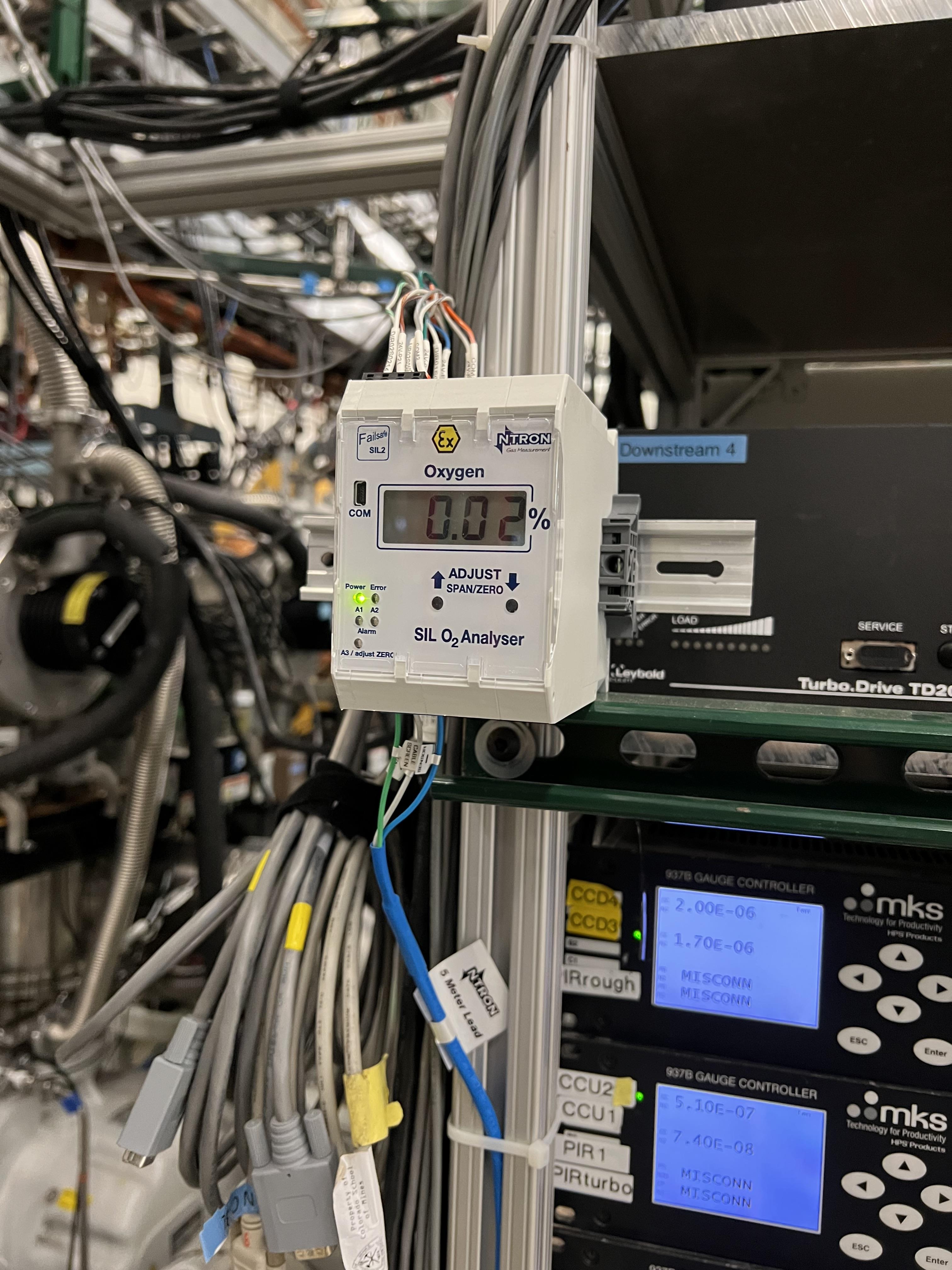
Fig. 4.35 The oxygen sensor’s controller is attached to the turbo pump controller panel (see Fig. 4.25)
A Parker excess flow valve (
V19: up to 3500 psi) with latching shutoff is installed on the hydrogen bottle (see Fig. 4.4) to mitigate bottle leak inside and outside vacuum. This valve is located between the hydrogen bottle valve and the pressure regulator installed on the hydrogen bottle. It automatically stops flow above 40 standard liters per minute, and is manually resettable.There are overpressure relief valves (see Fig. 4.8) implemented in the system and tied to the common vent, which is connected to the dedicated flammable gas exhaust of system, which is made of stainless steel and is grounded.
An emergency stop button (
) is implemented in the software and can be activated from any mode of operation to purge the system with dry nitrogen.MF7dilutes the exhaust with dry nitrogen with a ratio of 1:7 (\(H_{2}:N_{2}\)), limiting oxygen concentration at all times in all modes of operation.MF7uses laboratory supply of dry nitrogen and is constantly ON and has no interlocks on it for now. To avoid using too much of nitrogen, the plan is to install a valve downstreamMF7on the path to the exhaust and to have interlock on this valve such that it is only opened when the system is inventorpurgemode but these are not implemented yet. When the system is running a non-explosive gas, close MF7 to avoid wasting dry nitrogen. To do this:Using the probe functionality in CS-Studio, verify that
MF7is CLOSED: open the probe window and search this PV:SCR_BTS34:MFC_D1465A:MODE_CSET_MFC. Then, enterCLOSEunder new value and hitEnter. Make sure MF7 is open during hydrogen operation.
Warning
There is a needle valve upstream MF7 (see Fig. 4.13), which is set to a specific flow to avoid allowing too much dry nitrogen to be flushed down the exhaust through MF7. Please do not touch this needle valve to avoid changing its setpoint. It is set to allow 1000 sccm when MF7 flow setpoint is also set to 1000 sccm. Chaging this needle valve’s setpoint will cause too much usage of the dry nitrogen particularly if the MF7 flow setpoint is set to its maximum level, which is 50000 sccm. Please do not alter the flow setpoint of MF7 and leave it to be set to 1000 sccm all the times.
4.7.3. How to Change Hydrogen Bottle
Warning
Only hydrogen lead operators can change the hydrogen bottle
If at any time, the hydrogen bottle runs out of the supply gas and needs to be changed, follow the procedure below:
If the system is running with hydrogen and the system is in
runmode when the hydrogen bottle runs out:Stop the DAQ and scalers if they are running.
Safely de-bias the in-vacuum silicon detectors (see Section 10.1).
Verify
MF6isOPENand its flow rate is set to 1000 sccm.Using the probe functionality of CS-Studio, set the value of this PV:
SCR_BTS34:MFC_D1465F:MODE_CSET_MFCtoOPEN.Click on the
MF6indicator on the main control page (Fig. 4.1) and set the flow setpoint to 1000 sccm.
Click on E-stop button (
) to initiate a purge.Purge the system for 10 minutes.
After 10 minutes, click on the
button.
Switch to
ventmode and then immediately switch topumpmode and pump on the system for at least 15 minutes.Verify
V6is closed.Verify
V7andV3are also closed.Make sure the pressure gauges in the system read good vacuum (\(< 1\) Torr) in the system. Note that
SCR_BTS34:CMG_D1465Mshould read below 20 mTorr.Only then, it is safe to re-enter ReA3 vault (see Section 4.7.6).
Make sure you already have a cart to move gas bottles with, and you have snoop (a soapy mixture) ready.
Make sure you have a new full hydrogen bottle on the cart.
Follow the procedure to re-enter the ReA3 vault (see Section 4.7.6).
Once in the vault:
Make sure that the hydrogen bottle’s main valve on the empty bottle in the vault is fully closed before locking the gas bottle.
Switch to the maintenance operation mode (
MANmode).Verify
V1is open and the scroll pump is ON and all high vacuum pumps are still running.Close the small metallic valve after the hydrogen regulator near the flash arrestor (see Fig. 4.33).
Close the red excess flow valve labelled by
V19(see Fig. 4.4).Disconnect the gas bottle from the GHS. The explosive bottles are left handed. Use left handed rules to untighten the pipe fittings.
On the hose, there is a check valve that does not allow air to leak into the hose too much (see Fig. 4.36). So, the amount of oxygen that gets into the hose is very small and insignificant: nothing to worry about.
Remove the empty hydrogen bottle and move the full hydrogen bottle into its place.
Secure the new gas bottle by the belt which was around the empty gas bottle.
Connect the new gas bottle to the GHS pipes using left hand rules to tighten the pipe fittings.
Once the bottle is fully and securely attached to the GHS, open the red excess flow valve labelled as
V19.Open the small metallic manual valve passed the regulator upstream
V6and near the flash arrestor (see Fig. 4.33).Open the padlock on the hydrogen bottle.
Open the main bottle’s valve.
Pour snoop on the new gas bottle’s top area and the pipe fittings you just tightened and verify no bubbles are coming out.
Make sure the hydrogen regulator is set to 40 psi.
Immediately after, ask the OIC to perform sweep and lock of ReA3 high bay.
Follow the procedures found in DCC (Procedure to Secure ReA3 Hall for JENSA Extended Target Hydrogen Operation – Credited Administrative Control with ESH Impact; and FRIB-S30205-PR-001363-R001) to secure and exit the ReA3 vault.
Fig. 4.36 The check valve is the conical device at the end of the hose.
Once you are back to the DataU, access the CS-Studio control page.
Ideally, one would purge the system with the gas whose bottle was changed to remove any air bobbles but since the gas is hydrogen, we cannot purge the system with hydrogen, so we will fill the system with 10 Torr of hydrogen and then flush it out. This should remove the very small amount (about 1 – 2 cc) of air that is introduced into the system by the gas bottle exchange. To do this:
Switch to
Automode, and immediately without any delay switch topumpmode.Pump on the system for 5 minutes.
Then, fill the system with 10 Torr of hydrogen.
Switch to
runmode and run for 10 minutes.Press on the
to initiate a purge.Purge for 10 – 15 minutes.
Switch to
ventmode and then immediately switch topumpmode, and pump for 15 minutes.Switch to
fillmode and fill the system again with the desired pressure, and then go torunmode, and carry out the rest of the experiment.
4.7.4. What to Do prior to and during Hydrogen Operation?
The hydrogen lead operator(s) shall make sure that:
Prior to running the system with hydrogen, the hydrogen lead operator executes the complete Prestart Checklist for Hydrogen Operation of SECAR’s Extended Gas Target FRIB-M41600-TD-001693. (see also Section 4.7.5).
Make sure the reserved nitrogen bottle has enough nitrogen, and that both its manual valves (one on the bottle and one metallic one near the bottle on the regulator) are open. The regulator should be set to 15 psi and the bottle should be at least half full.
After the prestart checklist is performed, the ReA3 high bay has to be swept and locked properly following the Search and Evict Procedure for ReA3 Vault for JENSA Extended Target Hydrogen Operation – Credited Administrative Control with ESH Impact FRIB-M41600-PR-001653.
No personnel will be allowed to be present in the ReA3 high bay while the system is operating with hydrogen.
During hydrogen operation:
While running with hydrogen, monitor the oxygen content in the system. Oxygen sensor is sensitive down to \(0.01\%\). A standard Phoebus alarm will be triggered if the oxygen level in the system reaches \(0.1\%\). The target should then be pumped out and restarted with fresh gas. If there is a rapid rise press E-stop to initiate a purge.
If the oxygen level reaches \(0.4\%\), the system will be automatically switched to
purgemode.In case of an emergency and if you are in
runmode, click on the emergency stop button found on the operating mode controls section of the control page () to initiate a purge of the system with dry nitrogen.
4.7.5. How to Test the Oxygen Sensor’s Integrity
To ensure the oxygen sensor is calibrated correctly:
Everytime the system is fully vented and the chamber is open to air, check the oxygen monitor on the control page (see Fig. 4.1) . It should be reading around 19 - 20 percent.
There is a vent valve and its associated needle valve (see Fig. 4.18) for intentionally introducing air into the system when the system is fully ON and running and prior to hydrogen operation. These valves are used so that the hydrogen lead operator can check the interlocks that are set on the system regarding oxygen content of the gas target, while it is running hydrogen, to ensure those interlocks are working properly. To do this, prior to the hydrogen operation and as part of the prestart checklist, perform the following:
Notify the FRIB control room that they will hear a voice alarm related to oxygen content of the SECAR gas target.
Start operation of the gas target following Section 4.7.7.
Fill the system using helium or another non-explosive gas with the desired pressure.
Switch to
runmode.Then, open the valve with a black handle shown in Fig. 4.18.
Very slowly open the needle valve shown in Fig. 4.18 and carefully monitor:
The load on all turbo pumps (from their associated controllers found in Fig. 4.25.
The pressure gauges of the system.
The oxygen monitor.
Allow the oxygen content of the system to reach to \(0.4\%\) if the loads on the turbo pumps are managable.
When the oxygen content reaches \(0.1\%\), you should see a standard Phoebus alarm. Verify that this happens.
When the oxygen content reaches \(0.4\%\), the operators in the FRIB control room should hear a voice alarm. Verify that this too takes place.
When the oxygen content reaches \(0.4\%\), the system should also go into
purgemode. Verify that this occurs as well.Once the system goes into
purgemode:Close the needle valve and the valve with a black handle shown in Fig. 4.18.
Click on the
button found in “Operating Mode Controls” of the control page.Switch to
ventmode and then immediately switch topumpmode.
4.7.6. Locking and Re-entering into ReA3 Vault
The Hydrogen user in Charge (HUIC) can stop hydrogen operation to enable access to the ReA3 vault, can resecure the vault, and can restart hydrogen operation. The re-entry and search and evict proceduers in Search and Evict Procedure for ReA3 Vault for JENSA Extended Target Hydrogen Operation – Credited Administrative Control with ESH Impact FRIB-M41600-PR-001653. must be followed exactly. There are some additional considerations included in the checklists below:
Checklist for re-entry carried out by the HUIC
Stop run and unbias the PIPS detectors (see Section 10.1)
Switch to pump mode and evacuate target gas (gauges should read zero)
Close V3 and V6
Verify that SCR_BTS34:CMG_D1465M gauge reads <20 mTorr
Lock JENSA controls screen so that in your absence nobody can operate the target
Go to a ReA3 Vault door and open the card cover
Enter the ReA3 vault alone and immediately close and lock the main valve on the hydrogen bottle
The system is now in a safe state and others can enter
Report successful completion of the r-entry procedure to the FRIB control room and make an entry in the ELOG
Checklist for resecuring the ReA3 vault and restarting
Assign another hydrogen user to form a search team with you
Verify V3 and V6 are closed, pumps are running, and the system is still in pump mode and functioning properly
Ensure the two card reader covers for the doors to the ReA3 vault from HW13 hallway (along the west side of the ReA3 vault) are locked and signage is posted.
Lock one of the door card reader cover on the east side of the ReA3 vault and add signage, and enter the ReA3 vault via the last unlocked door (you can post signage to not enter).
Verify that chains to Penthouse are closed and locked - is that is the case you do not have to re-search the Penthouse. Otherwise carry out the search and evict procedure for the Penthouse following Search and Evict Procedure for ReA3 Vault for JENSA Extended Target Hydrogen Operation – Credited Administrative Control with ESH Impact FRIB-M41600-PR-001653.
Carry out search and evict procedure for the ground floor as described in Search and Evict Procedure for ReA3 Vault for JENSA Extended Target Hydrogen Operation – Credited Administrative Control with ESH Impact FRIB-M41600-PR-001653. to make sure noone other than the search team is in the vault.
Open unlock and open hydrogen bottle main valve before you leave the ReA3 vault (last thing before you leave). Check that pressure after regulator is between 30-50 psi.
Veerify that your search team partner has also exited the vault
Lock and post signage on the last open door
Report successful completion of the Search and Evict procedure to the FRIB control room and make an ELOG entry
In the data U, refill target
Once the target is operating at the nominal pressure, re-bias detectors
4.7.7. How to Operate the System with Hydrogen
Since a pre-start checklist (DCC Document FRIB-M41600-TD-001693-R001) should be followed prior to operation with hydrogen, this subsection assumes that the system is in pump mode to begin with and that all high vacuum pumps are ON. To do that, see Section 4.4.1. Zero the SCR_BTS34:CMG_D1465K, SCR_BTS34:CMG_D1465M and SCR_BTS34:CMG_D1465E capacitance manometer gauges (Section 4.4.3) if they show an offset and before you leave the ReA3 vault. Also, it is assumed that the ReA3 vault is fully secured and locked.
Once you are ready to fill the system with hydrogen:
Using the probe functionality in CS-Studio, verify that
MF7is OPEN: open the probe window and search this PV:SCR_BTS34:MFC_D1465A:MODE_CSET_MFC. Then, enterOPENunder new value and hitEnter.Verify that
MF4flow rate is set to 500 sccm.Verify that
MF2flow rate is set to 0 sccm.Switch to
fillmode.Set
MF2flow rate to \(100\) sccm.Monitor the pressures in various locations shown on the control page, as well as the oxygen level.
Note that the capacitance manometer
SCR_BTS34:CMG_D1465B(foreline),SCR_BTS34:CMG_D1465C(at the last DV650 pump),SCR_BTS34:CMG_D1465E,SCR_BTS34:CMG_D1465I,SCR_BTS34:CMG_D1465J,SCR_BTS34:CMG_D1465K(gas target), andSCR_BTS34:CMG_D1465M(below the gas target) all have interlocks on them (see Section 4.5.7), so pay a close attention to these pressures to avoid unnecessary purging later on.Once the pressure in the gas target (indicated by
SCR_BTS34:CMG_D1465K) reaches the desired value, set theMF2flow rate to 0 sccm.Switch to
runmode.Bias the silicon detectors (see Section 10.1) and keep monitoring the oxygen level properly via the CS-Studio archiver.
Adjust
MF4flow rate (it is recommended to set theMF4flow to its actual readback flow) to have a stable pressure within the gas target. Lowering the flow rate will reduce the pressure in the gas target and increasing the flow rate will increase the pressure in the gas target. Keep an eye on the foreline pressure and ensure it does not get near 500 Torr, which is the set point for an interlock, which causes the system to automatically switch to thepurgemode of operation.Monitor the pressures read by all cold cathode gauges, and all capacitance manometers.
The last ReA3 beamline gate valve (
ReA_BTS34:BGV_D1450) has an interlock with theSCR_BTS34:CCG_D1456cold cathode gauge, which is set to \(5\times10^{-7}\) Torr. If the pressure read by this gauge is above this limit, the beamline gate valve closes and cannot be opened until the pressure goes below the set point and after you reset this PV:SCR_BTS34:CCG_D1456:VAC_RST_CMD.The first SECAR beamline gate valve (
SCR_BTS35:BGV_D1483) has an interlock with theSCR_BTS34:CCG_D1471cold cathode gauge, which is set to \(1\times10^{-6}\) Torr. If the pressure read by this gauge is above this limit, the beamline gate valve closes and cannot be opened until the pressure goes below the set point and after you reset this PV:SCR_BTS34:CCG_D1471:VAC_RST_CMD.If you have to increase the pressure in the gas target:
If the pressure has to be increased just a bit, this may be achieved by adjusting
MF4. Keep in mind that the positive HV card supplying bias voltage to the in-vacuum PIPS detectors will shut down automatically if the pressure in the gas target goes above 25 Torr, or if the pressure read by the capacitance manometerSCR_BTS34:CGM_D1465M(pressure below the gas cell) reaches 10 mTorr while inrunmode of operation. Debias the silicon detectors safely (see Section 10.1) before these pressures are reached while the system is inrunmode.If the pressure increase is more than a few Torr:
Stop the DAQ and scalers first.
Debias the silicon detectors safely (see Section 10.1) before switching to
fillmode.Set
MF4flow rate to 500 sccm.Switch to
fillmode.Set
MF2flow rate to 100 sccm or lower to fill the gas target more slowly.Once desired pressure is reached in the gas target, set
MF2flow rate to 0 sccm.Switch back to
runmode and bias the PIPS detectors again.
If you have to pump the system while you are in the
runmode:Stop the DAQ and scalers.
Debias the silicon detectors safely (see Section 10.1).
Set
MF4flow rate to 500 sccm (fully open).Verify
MF2is set to 0 sccm.Switch to
fillmode, and immediately after, switch topumpmode.
If a purge occurs while you are in
runmode because some interlock is triggered:Let the purge continues for 10 minutes.
Click on
button.If you do not have to go to the ReA3 vault:
Verify that
V21is closed.Switch to
ventmode of operation.Switch to
pumpmode.Switch to
fillmode and fill the system again.Then switch back to
runmode and bias the PIPS detectors.
If you have to go enter the ReA3 vault, follow Section 4.7.6.
In case of an emergency:
Verify that
MF6is set to 1000 sccm.Click on
button, which will switch the system to purgemode. It is safe to keep purging the system for a long time assuming thatMF6is set to have a flow of 1000 sccm and that its upstream needle valve (see Fig. 4.6) was not touched.
4.7.8. Venting the System after Running with Hydrogen
MF6 is used to fill the system slowly with dry nitrogen while the system is in vent mode or purge mode. However, MF6 is typically set to have a flow rate of 1000 sccm, which is safe to purge the system while the turbo pumps are running but too slow for venting the system. The flow rate of 1000 sccm used for purging the system with dry nitrogen is set to achieve purging in a controlled manner; and therefore, the flow rate has to be small during the purge to avoid overwhelming the turbo pumps during this process.
Venting the system without changing MF6 flow rate may take many hours. As a result, V21 has been introduced into the system as of 4/9/2023 to enable venting the system with dry nitrogen in a faster and more efficient way. V21 valve is located on the path of the laboratory dry nitrogen supply line and downstream the needle valve (which should not be touched except by Brandon Ewert) that controls the flow of dry nitrogen into MF6 during a purge (see Fig. 4.6). V21 has its associated needle valve (see Fig. 4.29) attached to the dry nitrogen line downstream the V21 valve. This valve, in turn, is located downstream the purge needle valve (see Fig. 4.6). This allows the operator to avoid touching the needle valve upstream of MF6 used to set the dry nitrogen flow for purging, and therefore, keeping the purge flow at a low rate. But with the other needle valve near V21 and downstream of the purge needle valve, the operator can increase the flow of dry nitrogen through MF6 during venting via adjusting the correct needle valve (the one downstream V21, see Fig. 4.29) and by setting MF6 flow rate to 10000 sccm instead of 1000 sccm (used for purging) to allow a faster venting procedure. With this procedure, it still takes about 1 hour to vent the system! With the nitrogen regulator locked at 5 psi, the dry nitrogen flow rate through MF6 is about 7.4 standard liters per minute. The total volume of the system is about 421 liters. To speed up the process, one has to adjust the nitrogen regulator shown in Fig. 4.28 to allow a higher pressure of nitrogen to be reached. However, if you change this regulator, please remember to set it back to 5 psi and lock it towards the end of venting process and before the system is fully vented.
V21 valve can only be operated by switching into vent or MAN mode of operation. Its operation is manually commanded by the operator via the control software while the system is in vent or MAN mode: only in these two modes of operation, operator can choose to open/close V21 valve.
To vent the system, do the following:
If the system is in
runmode:Stop DAQ and scalers.
Safely debias the PIPS detectors.
Verify
MF6is set to have a 1000 sccm flow rate.Press on the
button to initiate a purge.Keep purging for 10 minutes.
Press on the
button.Switch to
ventmode.Switch to
pumpmode.Pump the system for at least 15 minutes.
Follow the procedures presented on point 3 below.
If the system is in
fillmode when it is decided to vent the system:Set
MF2to 0 sccm.Switch to
pumpmode.Follow the procedures presented on point 3 below.
If the system is in
pumpmode and would like to vent the system:Verify that the hydrogen is safely evacuated from the system by verifying the pressures read from capacitance manometer gauges at various locations. They should be below 1 Torr.
SCR_BTS34:CMG_D1465Mshould read below 20 mTorrNow it is safe to follow the procedures discussed in Section 4.7.6 to enter the ReA3 vault.
While in the vault, and while the system is still in the
pumpmode, turn OFF all the high vacuum pumps (see Section 4.4.2).Wait till all turbo pumps spin down to zero. Put your hands on each turbo pump and ensure they are not vibrating (indicating they are still spinning). Turn OFF the water lines and fans.
Switch to
ventmode.Verify that the dry nitrogen regulator (see Fig. 4.28) is locked on 5 psi.
Verify
MF4is open and its flow rate is set to 500 sccm. If not, set it to 500 sccm.Open
V21.Verify
MF6is open.Set
MF6to 10000 sccm.Monitor the pressure gauges. If they are coming up too slowly, open all the way the metallic needle valve that is associated with
V21(see Fig. 4.29). If the system is venting too quickly, reduce the flow rate ofMF6to 5000 sccm and/or adjust the metallic needle valve that is associated withV21. Once the pressure gauges read 730 – 760 Torr, the system is fully vented. Note thatSCR_BTS34:CMG_D1465KandSCR_BTS34:CMG_D1465Mwill only read 100 Torr and 1 Torr, respectively. With the nitrogen regulator locked at 5 psi, the dry nitrogen flow rate throughMF6is about 7.4 standard liters per minute. The total volume of the system is about 421 liters so it takes a bit more than 1 hour to vent the system.Close
V21.Close the needle valve downstream
V21used for venting (see Fig. 4.29).Set
MF6flow rate back to 1000 sccm.Switch to
MANmode and closeV13.
If the system is in
MANmode prior to venting:- With the system under configuration to run hydrogen, this item should only happen when you re-enter the ReA3 vault to exchange the hydrogen bottle. Only in this case, follow this instruction as it is safe to assume that the gas handling system and the gas chamber are already safely evacuated from hydrogen prior to getting to this step.
Verify
MF6is set to 1000 sccm and is open.Verify
V6andV3are closed.Verify the JENSA scroll pump is ON and
V1is open.Turn OFF all high vacuum pumps (see Section 4.4.2).
Wait till all turbo pumps spin down to zero. Put your hands on each turbo pump and ensure they are not vibrating (indicating they are still spinning). Turn OFF the water lines and fans.
Verify that the dry nitrogen regulator (see Fig. 4.28) is locked on 5 psi.
Verify
MF4is open and its flow rate is set to 500 sccm. If not, set it to 500 sccm.Close the manual roughing valve on the JENSA scroll pump (
VROUGH)Open
V13andV21.Set MF6 to 10000 sccm.
Monitor the pressure gauges. If they are coming up too slowly, open all the way the metallic needle valve that is associated with
V21(see Fig. 4.29). If the system is venting too quickly, reduce the flow rate ofMF6to 5000 sccm and/or adjust the metallic needle valve that is associated withV21. Once the pressure gauges read 730 – 760 Torr, the system is vented. Note thatSCR_BTS34:CMG_D1465KandSCR_BTS34:CMG_D1465Mwill only read 100 Torr and 1 Torr, respectively. With the nitrogen regulator locked at 5 psi, the dry nitrogen flow rate throughMF6is about 7.4 standard liters per minute. The total volume of the system is about 421 liters so it takes a bit more than 1 hour to vent the system.Close
V21andV13.Close the needle valve downstream
V21used for venting (see Fig. 4.29).Set
MF6flow rate back to 1000 sccm.
If the system automatically switched to
ventmode due to a fault (such as failure of the JENSA scroll pump):This could happen while the system was in
pumpmode orpurgemode prior to switching toventmode. Either way, most of the hydrogen should have been removed from the system. To ensure this is the case:Monitor the capacitance manometer pressure gauges and when the gas target pressure is about 20 Torr, follow instructions given in Section 4.7.6 and re-enter the ReA3 vault. Here, we are assuming that there is enough dry nitrogen in the system that hydrogen is diluted below its lower explosive limit.
Turn OFF all high vacuum pumps per instructions given in Section 4.4.2.
Wait till all turbo pumps spin down to zero. Put your hands on each turbo pump and ensure they are not vibrating (indicating they are still spinning). Turn OFF the water lines and fans.
Verify that the dry nitrogen regulator (see Fig. 4.28) is locked on 5 psi.
Verify
MF4is open and its flow rate is set to 500 sccm. If not, set it to 500 sccm.Open
V21.Set
MF6to 10000 sccm.Monitor the pressure gauges. If they are coming up too slowly, open the metallic needle valve that is associated with
V21(see Fig. 4.29). If the system is venting too quickly, reduce the flow rate ofMF6to 5000 sccm and/or adjust the metallic needle valve that is associated withV21. Once the pressure gauges read 730 – 760 Torr, the system is vented. Note thatSCR_BTS34:CMG_D1465KandSCR_BTS34:CMG_D1465Mwill only read 100 Torr and 1 Torr, respectively. With the nitrogen regulator locked at 5 psi, the dry nitrogen flow rate throughMF6is about 7.4 standard liters per minute. The total volume of the system is about 421 liters so it takes a bit more than 1 hour to vent the system.Close
V21and its needle valve.Set
MF6flow rate back to 1000 sccm.Switch to
MANmode and closeV13.
4.7.9. Changing to Manual Mode during Hydrogen Operation
This mode of operation is where the operator is able to command all valves (except V15, which is interlocked with the flow rate of MF6, see Section 4.5.7) manually via the software control. I would recommend that this mode is not operated during hydrogen operation at all unless the hydrogen bottle has to be exchanged (see Section 4.7.3). Operating this mode for any other reason during hydrogen operation is a dangerous action and shall be avoided if hydrogen is in the system unless the operator is a system expert. The instructions below should only be followed if the automatic purging has failed for some reason.
Warning
Following this instruction requires expert knowledge of the system. If you are not a system expert, STOP right now!
If for whatever weird reason, the automatic purging failed and/or something weird is happening with the software control in the operating mode you are running the system with:
Stop the DAQ and scalers.
Safely debias the PIPS detectors if they are still ON.
Switch to
MANmode.Verify
V6,V7,V3, andV10are all closed. If not, close them all (V6first).Verify
V12andV2are open.Verify scroll pump is ON. It should be green.
Verify
MF6is set to 1000 sccm.Open
V1andV13.Verify
MF4is open and its flow rate is set to 500 sccm. If not, set it to 500 sccm.Now, you should be purging the system with dry nitrogen. Keep purging for 10 minutes.
After 10 minutes, close
V13. Now, the system is being pumped on. Keep pumping for at least 15 minutes until all capacitance manometer pressure gauges of the system read 1 Torr or below.
4.7.10. Emergency Shutdown Procedure while Running with Hydrogen
In case of an emergency:
Verify that
MF6is set to 1000 sccm.Click on
button, which will switch the system to purgemode. It is safe to keep purging the system for a long time assuming thatMF6is set to have a flow of 1000 sccm and that its upstream needle valve was not touched.
After the emergency situation is over and things are back to normal, you need to:
Click on the
button.Switch to
ventmode.Switch to
pumpmode.If the experiment is still going on, swicth to
fillmode. Fill the system again and switch torunmode and carry on with the rest of the experiment.
In a rare case of a total loss of network access that lasts for more than a few minutes, if vault access is needed, the hydrogen lead operator follows the procedure in Search and Evict Procedure for ReA3 Vault for JENSA Extended Target Hydrogen Operation – Credited Administrative Control with ESH Impact FRIB-M41600-PR-001653:
We will install a physical E-STOP button at the entrance of the ReA3 Hall (west side). If that button is installed press it.
Take a remote reading of the oxygen level in the gas target. We will have remote reading without network enabled - either by an external display next to the above mentioned E-STOP button, or a wired camera feed in the data U. - If the reading is less than 0.4% proceed. - If the reading is moree than 0.4% the equivalent protection process must be followed
If oxygen level is below 0.4% enter vault alone
Close and lock valve on hydrogen bottle
Execute manual purging procedure described beelow
To stop the hydrogen operation, do the following only if you are the system expert (or hydrogen lead operator):
Go to the panel, where all the gauge controllers are (see Fig. 4.25). Find
MKS5controller (see Fig. 4.37).Using the up/down arrow buttons, select
CMG D1465K. Once it is seleceted, you will see a green LED light next to this label.Push on the
System Setupbutton. The display should now look like Fig. 4.38.Keep pressing the down arrow button until the
Set Paramis highlighted with a blue color.Press on the
Enterbutton. The highlight will become black. Press on the up arrow button once. The highlighted text should now be changed toEnable.Press on the
Enterbutton again. Then press onESCbutton.Press on the
Channel Setupbutton. Now, the dispay should look like Fig. 4.39.Use the up/down and left/right arrow buttons and select the
Enabletext to the right ofRelay 09.Press on the
Enterbutton. TheEnabletext will become black.Press the up or down arrow button until
Enablechanges toSet.Once the entry reads
Set, press on theEnterbutton again.Press the
ESCbutton.Now, the interlock on the pressure of the gas cell will force the system to go into
purgemode. It is safe to leave the system inpurgemode until the emergency situation is dealth with.Leave ReA3 vault according to the procedures mentioned in Section 4.7.6.
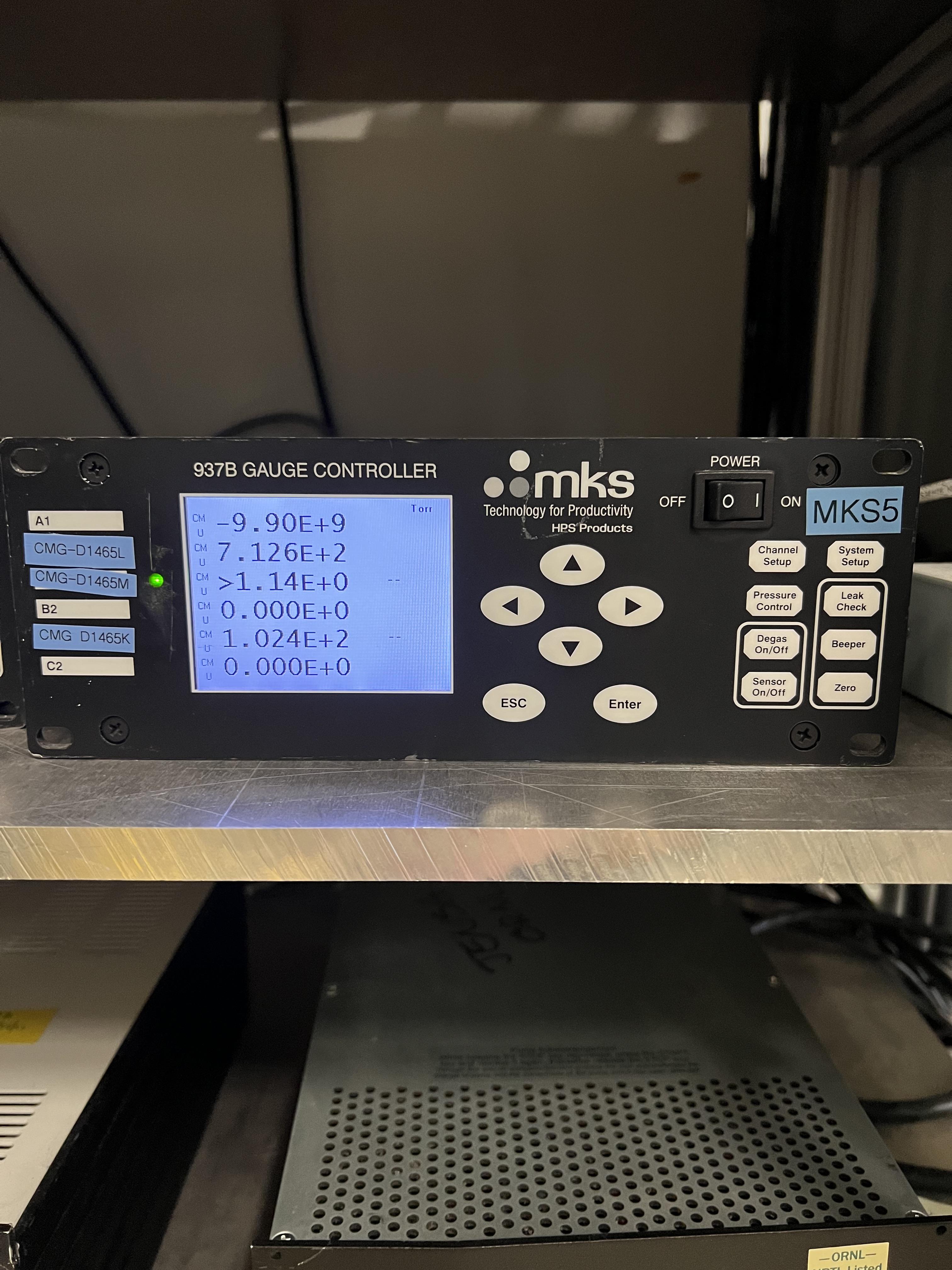
Fig. 4.37 The MKS5 unit controls the capacitance manometers SCR_BTS34:CGM_D1465K (reads the pressure in the gas cell), SCR_BTS34:CGM_D1465L, and SCR_BTS34:CGM_D1465M.
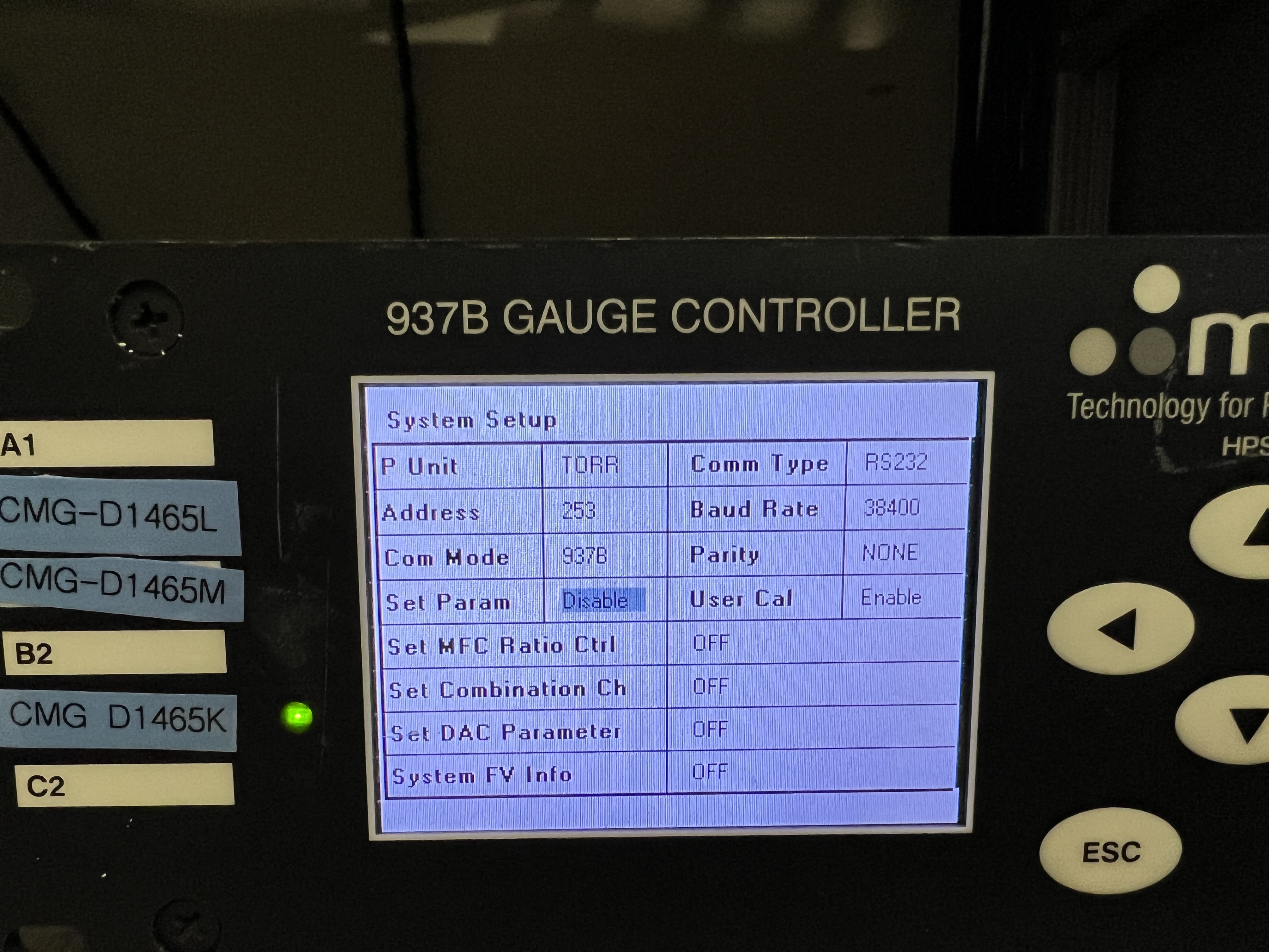
Fig. 4.38 The Set Param setting lets you enable or disable setting the parameters manually using the controller. Please make sure that this setting is set by default to be Disabled for all capacitance manometer gauge controllers of the GHS so that non-experts cannot change system interlocks.
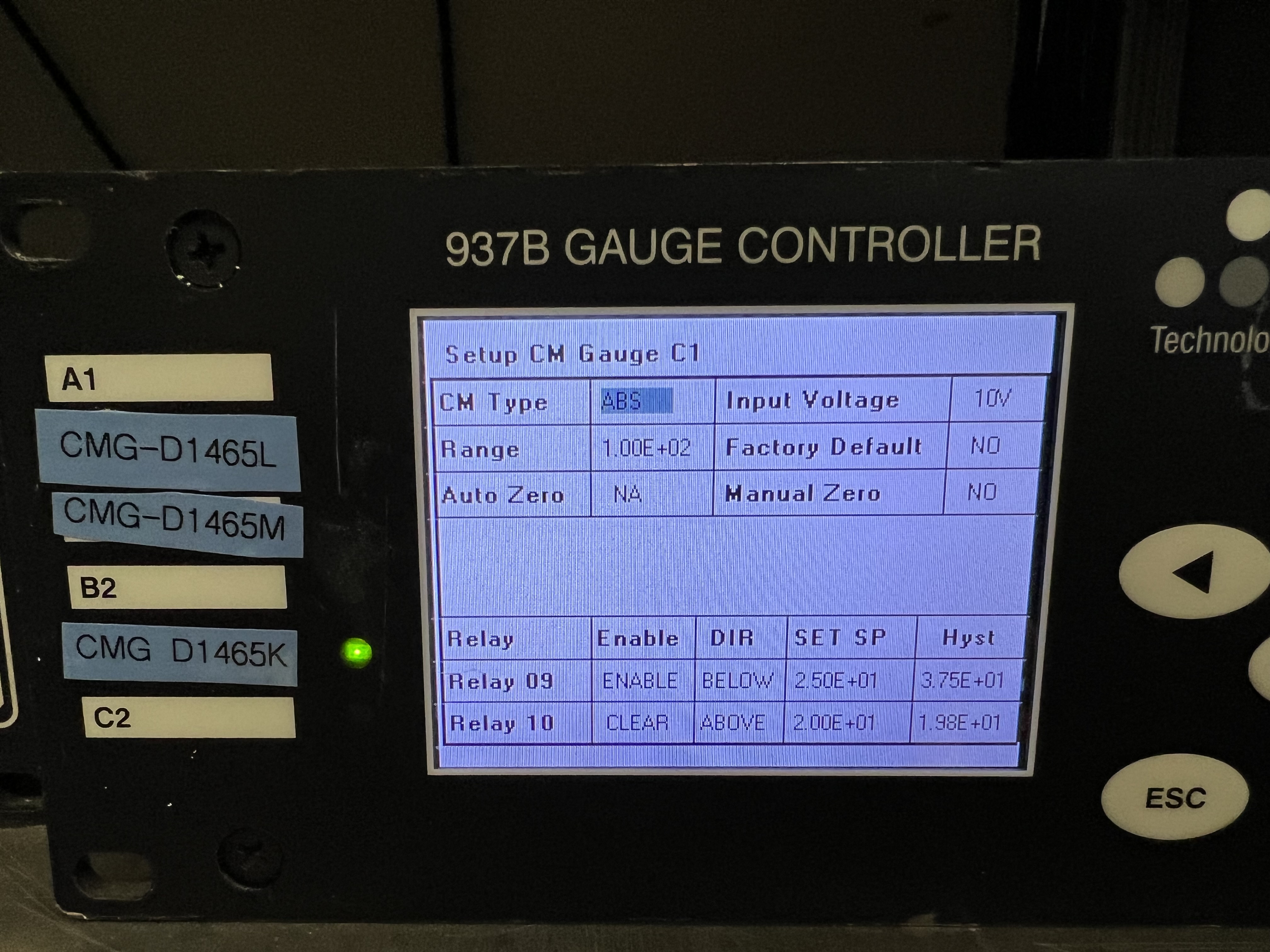
Fig. 4.39 Using Channel Setup, you can set the interlock. Please avoid changing the interlocks if you are not a system expert.
Important
After it is safe to go back to the ReA3 vault, please go back and undo what you did before by doing the following steps:
Reset the interlock for the gas cell’s pressure on
MKS5controller unit:Press on the
Channel Setupbutton. Now, the dispay should look like Fig. 4.39.Use the up/down and left/right arrow buttons and select the
Settext to the right ofRelay 09.Press on the
Enterbutton. TheSettext will become black.Press the up or down arrow button until
Setchanges toEnable.Once the entry reads
Enable, press on theEnterbutton again.Press the
ESCbutton.
Disable the
Set Paramof theMKS5unit again by following the procedures below:Push on the
System Setupbutton. The display should now look like Fig. 4.38.Keep pressing the down arrow button until the
Set Paramis highlighted with a blue color.Press on the
Enterbutton. The highlight will become black. Press on the up arrow button once. The highlighted text should now be changed toDisable.Press on the
Enterbutton again. Then press onESCbutton.
Click on the
button found under “Operating Mode Controls” part shown in Fig. 4.1. Switch to ventmode, and immediately after, switch topumpmode. If you need to carry on with the experiment:Swicth to
fillmode, fill the system with the desired pressure and then switch to therunmode and bias the PIPS detectors.
4.8. Operation of the Target Detectors
This section desribes all you need to know to be able to operate the detectors that are used in and out of vacuum together with the extended gas target, as well as the jet target.
4.8.1. The JENSA CAEN Power Supply for the Silicon and BGO Detectors
The power supply for silicon and BGO detectors is a CAEN SY 2527 LC Universal multichannel power supply system. There are currently 4 HV cards in this power supply:
One positive HV card, which is used to bias the PIPS detectors used inside the vacuum chamber.
Three negative HV card to bias the BGO detectors used outside the vacuum chamber surrounding it.
The power supply can be operated in local or remote control, which are accessible by turning the key (see Fig. 4.40) into each position (as well as the OFF position, which turns the power supply entirely OFF) from the front face of the power supply.
Local mode of operation: this mode of operation should not be used unless a system expert desires to test something.
Remote mode of operation: this mode of operation is what should be used with both SECAR’s gas targets. Make sure the key (see Fig. 4.40) is always in this position unless for some reason the power supply has to be unplugged, in which case, after turning the power supply OFF (see Section 4.8.4), you should move the key into OFF position.
There is a small power supply that is attached to the top of the JENSA electronics rack (SECAR R1421 CAB N0303) visible in Fig. 4.41, which changes the 24V signal outputted by the PLC to a 12V signal and vice versa to enable the communication between the PLC and the JENSA CAEN power supply (Fig. 4.40).
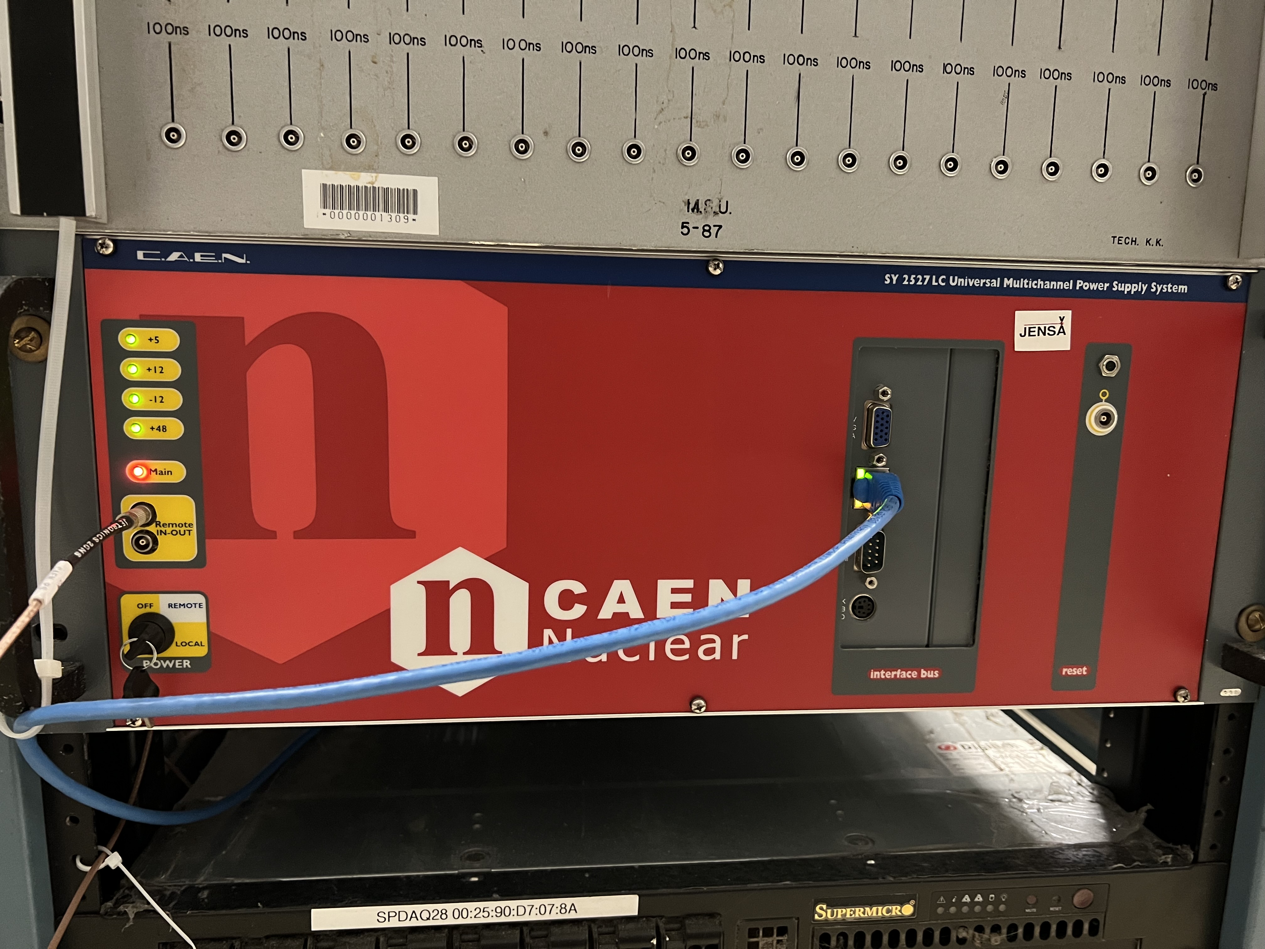
Fig. 4.40 This CAEN power supply is located at the bottom of the JENSA electronics rack (SECAR R1421 CAB N0303) found near SECAR’s target. There are 3 operation modes defined by the location of the black key: local, remote and OFF. Make sure the key is always in the remote position unless the power supply has to be unplugged, in which case, the key needs to be shifted into OFF position. The red main LED indicates the power to the power supply is ON.
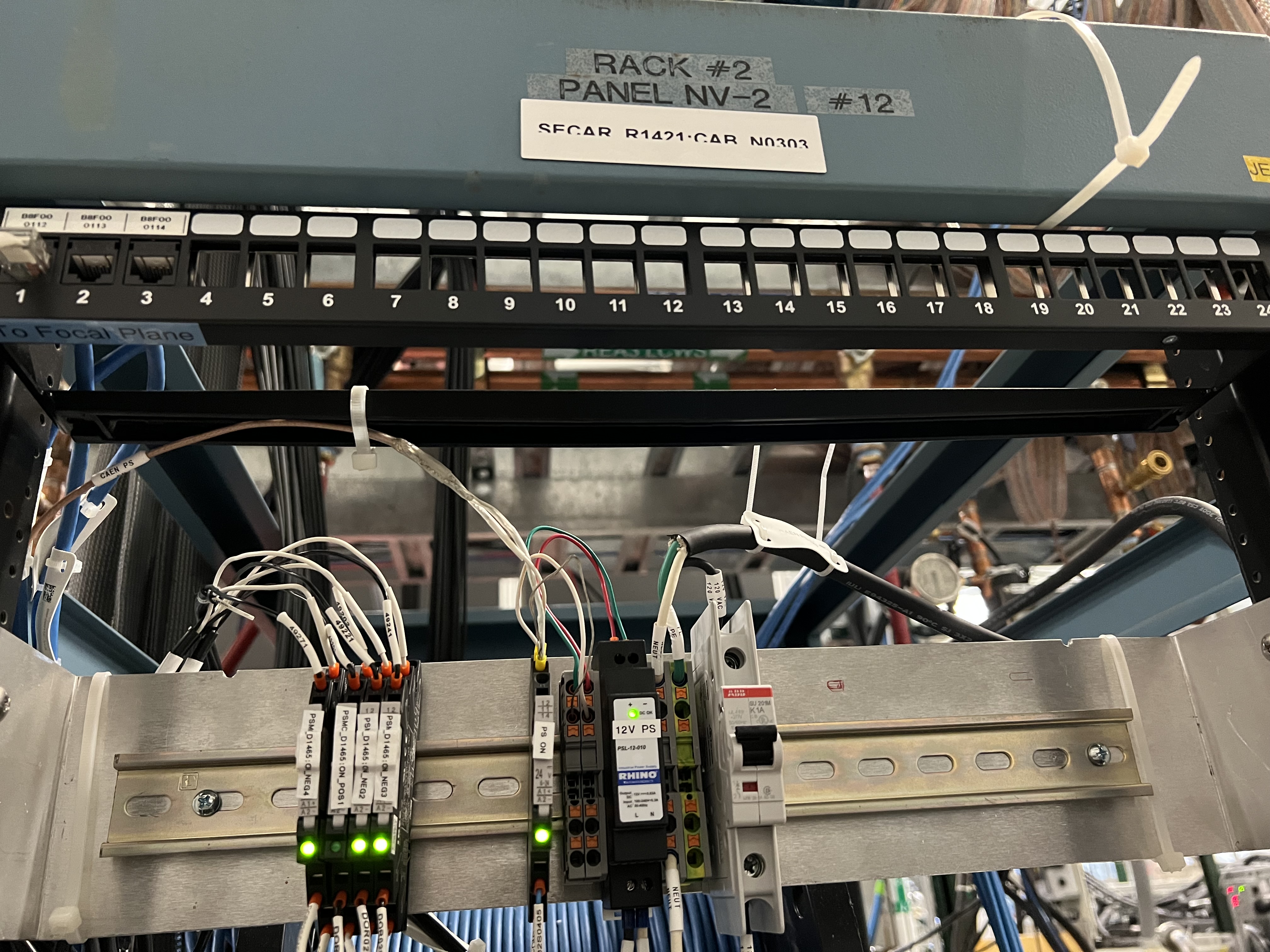
Fig. 4.41 The power supply labelled as “12V PS” changes the 24V signal used by the PLC to a 12V signal used by the JENSA CAEN power supply to enable the communication between the PLC and the CAEN power supply. The other units on the left side of the image are the relays for the HV cards (see Section 4.8.2).
4.8.2. High Voltage Cards
The HV cards providing bias to any detector that is powered by the JENSA CAEN power supply are found inserted (Section 4.8.5) to the back of the main power supply (see Fig. 4.42). At the moment, there are 4 of these cards inside the JENSA CAEN power supply:
One provides positive voltage (up to 1.5 kV) and has an interlock set on it. This card is used for the two PIPS detectors used inside the vacuum chamber.
Three cards provide negative voltage (up to 1.5 kV) and have no interlock set on them. These cards are used with the 26 BGO detectors that surround the extended gas cell.
At the right top side of each of these cards, you will see a LEMO input called “HVEN”, where there is a LEMO cable connected labelled as:
POS1for the HV card with positive voltage output.NEG4,NEG2, andNEG3(from top to bottom) for the HV cards with negative voltage output.
All these cables are going into separate relays (see the devices on the left side of Fig. 4.41) labelled as PSMC_D1645:ON_POS1, PSMC_D1645:ON_NEG4, PSMC_D1645:ON_NEG2, and PSMC_D1645:ON_NEG3. All these relays are normally open (in the case of no actuation and/or no power, the relay is OFF and the circuit is open). The last 3 relays (for negative HV cards) currently do not have any interlock set on them but the relay labelled as PSMC_D1645:ON_POS1 (used with the positive HV card supplying bias to the PIPS detectors) has an interlock set on it. If any of these relays is energized, it will allow a 50 Ohm resistor to be attached accross the “HVEN” input of the HV card, to which the relay is connected. The presence of this 50 Ohm resistor on the “HVEN” input of each of the HV card is necessary for all the 12 bias outputs of the HV card to be enabled. Since the BGO detectors are outside the vacuum and are not under hydrogen atmosphere, they are not considered sources of ignition. Therefore, the 3 relays connected to the three negative HV cards are always ON (as long as they have power) and the 50 Ohm resistors are always attached across the “HVEN” inputs of these cards. So, all those 36 bias channels are always enabled as long as those relays are energized. The PIPS detectors, on the other hand, are being operated inside the vacuum chamber where hydrogen could be flowing. To rule out the PIPS detectors as a source of ignition during hydrogen operation, we have set an interlock on the relay for the positive HV card such that it can only be energized when:
The system is in
runmode of operation ANDAfter the
button found under “Operating Mode Controls” of the control page (see Fig. 4.1) is clicked once when the system is in runmode ANDThe gas cell has a pressure that is below 25 Torr AND
The chamber underneath the gas cell has a pressure below 10 mTorr AND
The oxygen cotent of the system is below \(0.4\%\).
If any of these conditions is not met, the relay will be de-energized and the 50 Ohm resistor accross the “HVEN” input of the positive HV card will disappear. This then immediately disables all the 12 bias output channels of this HV card and the PIPS detectors will be immediately debiased as a result.
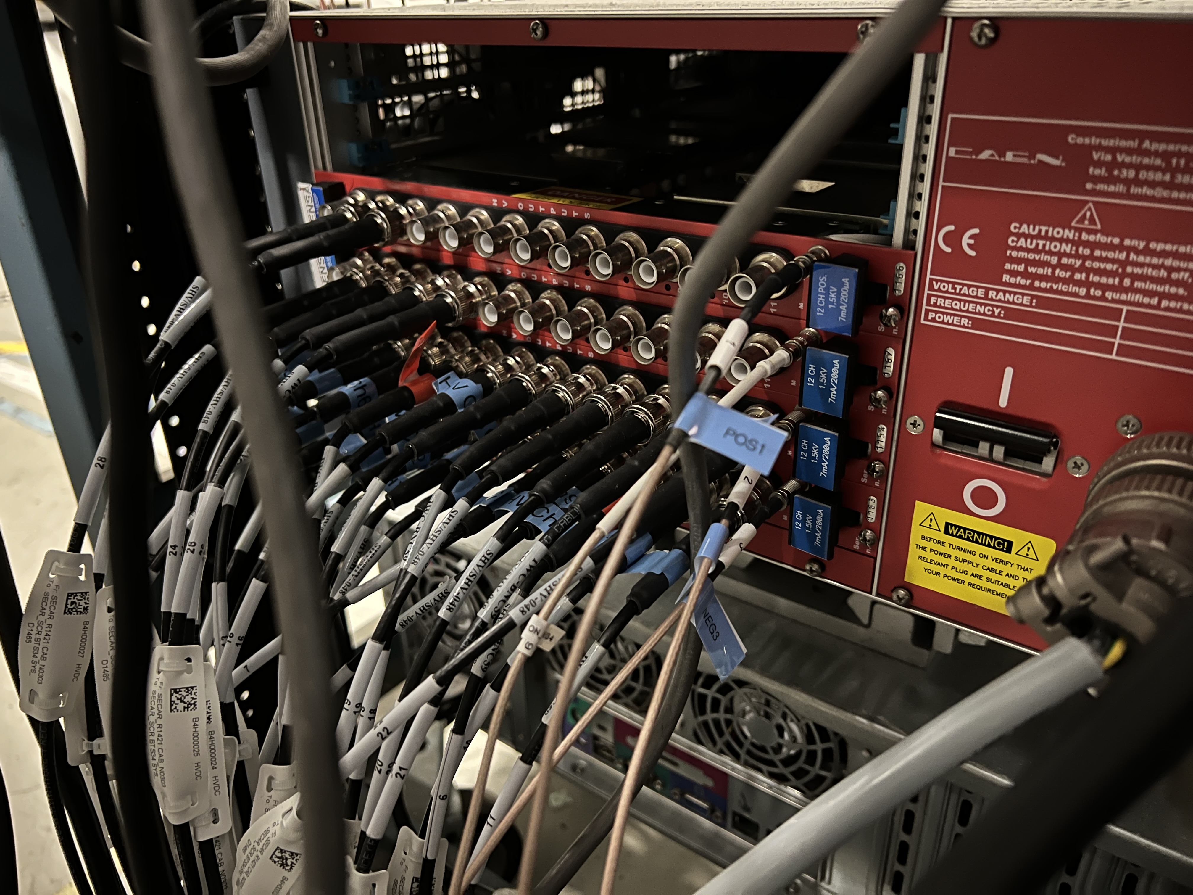
Fig. 4.42 There are 4 HV cards inserted to the back of the JENSA CAEN power supply. Each of them has 12 bias output channels. One of these cards provides positive HV up to 1.5 kV, while the other 3 provide negative HV up to 1.5 kV. The two PIPS detectors are connected to the positive HV card. The negative HV cards provide bias to all 26 BGO detectors that surround the extended gas target.
4.8.3. How to Operate the JENSA CAEN Power Supply
To operate the JENSA CAEN power supply:
Make sure the black key found on the front face of the power supply is pointing towards remote.
Look at the
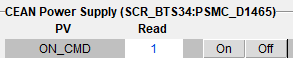 section of the GHS control page (see Fig. 4.1):
If the value under “Read” column and along the
ON_CMDrow is 0: click on theOnbutton.If this value is 1, the JENSA CAEN power supply is already ON.
Look at the
 section of the GHS control page (see Fig. 4.1):
If the value under “Read” column and along the
EN_CMD_POS1row is 0: click on theOnbutton. You can only turn this ON if:The mode of operation currently selected is
runmode ANDThe
button found under “Operation Mode Controls” of the control page is pressed ANDThe pressures in the gas cell and immediately below the gas cell are below 25 Torr and 10 mTorr, respectively, AND
The oxygen content of the system is below \(0.4\%\).
If this value is 1, the positive HV card of the JENSA CAEN power supply is already ON.
Look at the
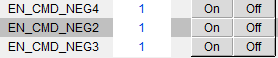 section of the GHS control page (see Fig. 4.1):
If the values under “Read” column and along the
EN_CMD_NEG2(andEN_CMD_NEG3andEN_CMD_NEG4) rows are 0: click on theOnbuttons.If these values are 1, the negative HV cards of the JENSA CAEN power supply are already ON.
On a linux computer that is connected to the DAQ network, open a terminal and do the following:
     cd ~
     startev
     caen_supply
     # the above command is an alias for: telnet 10.65.50.95 1527
     # The IP address of the power supply is 10.65.50.95
     # The port used is 1527
A new window pops up (see Fig. 4.43).
Press any key to be able to enter the login credentials (Fig. 4.44).
Enter the login credentials. If you make a mistake, you cannot use backspace and correct the typo. Just hit
Entertwice. You will be redirected to the same login page. Enter your credentials correctly again.Press
Enter.Using the down arrow button on the keyboard, select
Channelsand pressEnter.Now, the display looks like Fig. 4.45.
Click anywhere on the GUI and use the up/down and left/right arrows to move to any of the inputs.
The nomenclature is as follows:
Every 12 channels (12 rows) correspond to one HV card, which is shown by
Ch#.Ch# 00refers to the negative HV card labelled asPSMC_D1465:ON_NEG3. This section has 12 subsections labelled as00.0000to00.0011. These are the 12 bias output channels of this HV card.Ch# 01refers to the negative HV card labelled asPSMC_D1465:ON_NEG2. Subsections are same as above,Ch# 02refers to the negative HV card labelled asPSMC_D1465:ON_NEG4. Subsections are same as above.Ch# 03refers to the positive HV card labelled asPSMC_D1465:ON_POS1. All 12 channels of this section are disablled initially until the gas target is switched torunmode of operation and the button is clicked AND only if the pressures of the gas target and below the gas cell are lower than 25 torr and 10 mTorr, respectively AND the oxygen content of the system is below \(0.4\%\).
Channel Nameis a given name for a bias channel output of the HV card. Usually, we use the detector names as channel names.V0Setis the voltage setpoint for a particular channel.I0Setis the allowed leakage current set point for a particular channel.VMonis the live readback of the voltage applied to a particular channel.IMonis the live readback of the leakage current of a particular channel.Pw Statusdisplays the power state of a particular channel (ON or OFF).Tripis always set to 1 seconds and shows how soon a channel should trip if the actual leakage current (IMon) goes above the set point (I0Set).SVMaxis the maximum voltage that can be applied to a channel and this should be set to 1500 V because none of the HV cards of this power supply can provide more than 1.5 kV.Set
V1Setto 0V. I do not know what this is!I1Setis the maximum leakage current that is allowed. Leave it at 500 \({\mu}A\) unless you want to set to a lower current for a particular sensitive detecor.RDWnis the voltage ramp down rate in (V/s).Set
TripIntto 0. This is internal trip and I am not sure why it has to be set to 0.Set
TripExt BdStatusto 16. This is external trip and I do not know why it has to be set to 16.Leave
HVMaxalone. I do not know why they are all around 2 kV. This is not an editable field anyway.Tempshows you temperature in Celsius.RUis the voltage ramp up rate (in V/s).Set
POntoDis. I do not remember what this refers to.PDwncan be eitherKillorRamp. It supposedly either ramps down a channel’s HV or kills the HV (ramps down immediately to 0 V) in case of a trip. But what I have observed with this power supply is that even if you chooseKill, it seems to always ramps down a channel, which is not a bad thing.
If the desired
Channel Name, itsVOSetandI0Set(voltage and leakage current set points) are already set and you are only interested to turn that channel ON/OFF:Use the arrow keys on the keyboard, go to the desired channel.
Select the text under
Pw(power) column.Hit the
spacebaron the keyboard to switch the channel ON/OFF. If the bias was ON, it will be turned OFF and vice versa.
If you would like to set some or all of the aforementioned inputs:
If the channels are flashing, they are disabled. This could be the case for the positive HV card that has an interlock on it for hydrogen operation.
Use the arrow keys on the keyboard, go to the desired input.
Start typing the desired values. If at any point, you made a mistake, there is no way you can use backspace to correct the typo. Just hit the
tabbutton on the keyboard. This will undo what you did. Then hitEntertwice and you will get back to where you were.Hit the
spacebaron the keyboard to toggle through the available inputs such as ON/OFF, Ramp/Kill etc.Make sure you set the channel name (to something easily recognizable), voltage and current set points, ramp down/up rates, and maximum allowed voltage and current for any new detector setup.
Once you are done, hit the
tabbutton on the keyboard. PressEnter. Use the down arrow button of the keyboard and selectLogout. PressEnter.Exit from the terminal and log out of the experimental account.
Warning
After turning the JENSA power supply to local mode of operation if it was in remote mode, or vice versa, you will need to wait for about 50 seconds before the power supply resets itself and becomes available for communication through telnet. During this more or less 50 seconds, you will not be able to ping the power supply or communicate with it using its GUI.
Note
Operation of the JENSA CAEN power supply in the local mode is identical to that in remote mode; however, you would need to replace all the relay cables with 50 Ohm LEMO terminators that are plugged directly into the “HVEN” inputs of all the HV cards to enable the HV outputs. This means that you will lose the ability to have any interlock on any of the HV output channels. So, it is crucial that the power supply is operated in remote control during hydrogen operation to be able to have an interlock on the PIPS detectors.
Fig. 4.43 The login page of the JENSA CAEN power supply GUI.
Fig. 4.44 Enter the credential to be able to access the JENSA CAEN power supply’s GUI.
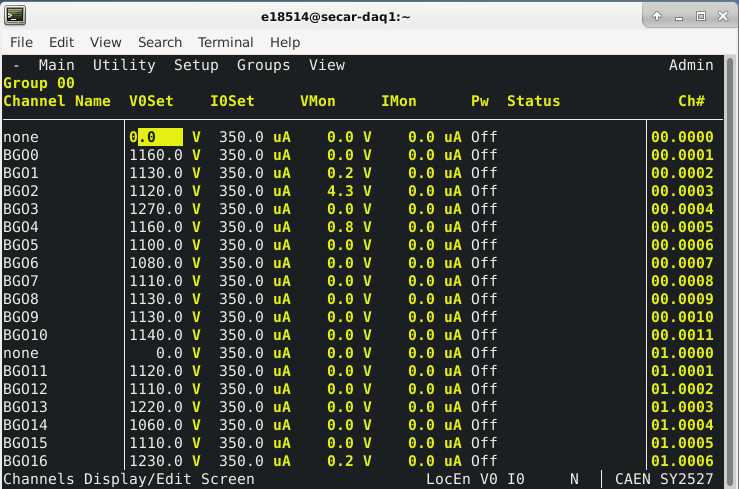
Fig. 4.45 The JENSA CAEN power supply’s GUI.
4.8.4. How to Turn the CAEN Power Supply OFF
If the power supply has to be unplugged, or if a new HV card is to be inserted into the JENSA CAEN power supply, you need to first turn it OFF. To do so:
Make sure all the detectors that are connected to this power supply through its HV cards are safely debiased (see Section 4.8.3).
Close the GUI used for operation of the power supply (see Section 4.8.3)
Look at the
section of the GHS control page (see Fig. 4.1):If the value under “Read” column and along the
ON_CMDrow is 1: click on theOffbutton.If this value is 0, the JENSA CAEN power supply is already OFF.
Look at the
section of the GHS control page (see Fig. 4.1):If the value under “Read” column and along the
EN_CMD_POS1row is 1: click on theOffbutton. You can only turn this OFF if:The mode of operation currently selected is
runmode ANDThe
button found under “Operation Mode Controls” of the control page is pressed ANDThe pressures in the gas cell and immediately below the gas cell are below 25 Torr and 10 mTorr, respectively, AND
The oxygen content of the system is below \(0.4\%\).
If this value is 0, the positive HV card of the JENSA CAEN power supply is already OFF or disabled (because the conditions mentioned above are not met).
Look at the
section of the GHS control page (see Fig. 4.1):If the values under “Read” column and along the
EN_CMD_NEG2(andEN_CMD_NEG3andEN_CMD_NEG4) rows are 1: click on theOffbuttons.If these values are 0, the negative HV cards of the JENSA CAEN power supply are already OFF.
Turn the black key found on the front face of the power supply to OFF position.
Turn the power button, found at the back of the power supply (where the HV cards can be seen, see Fig. 4.46) downward to 0.
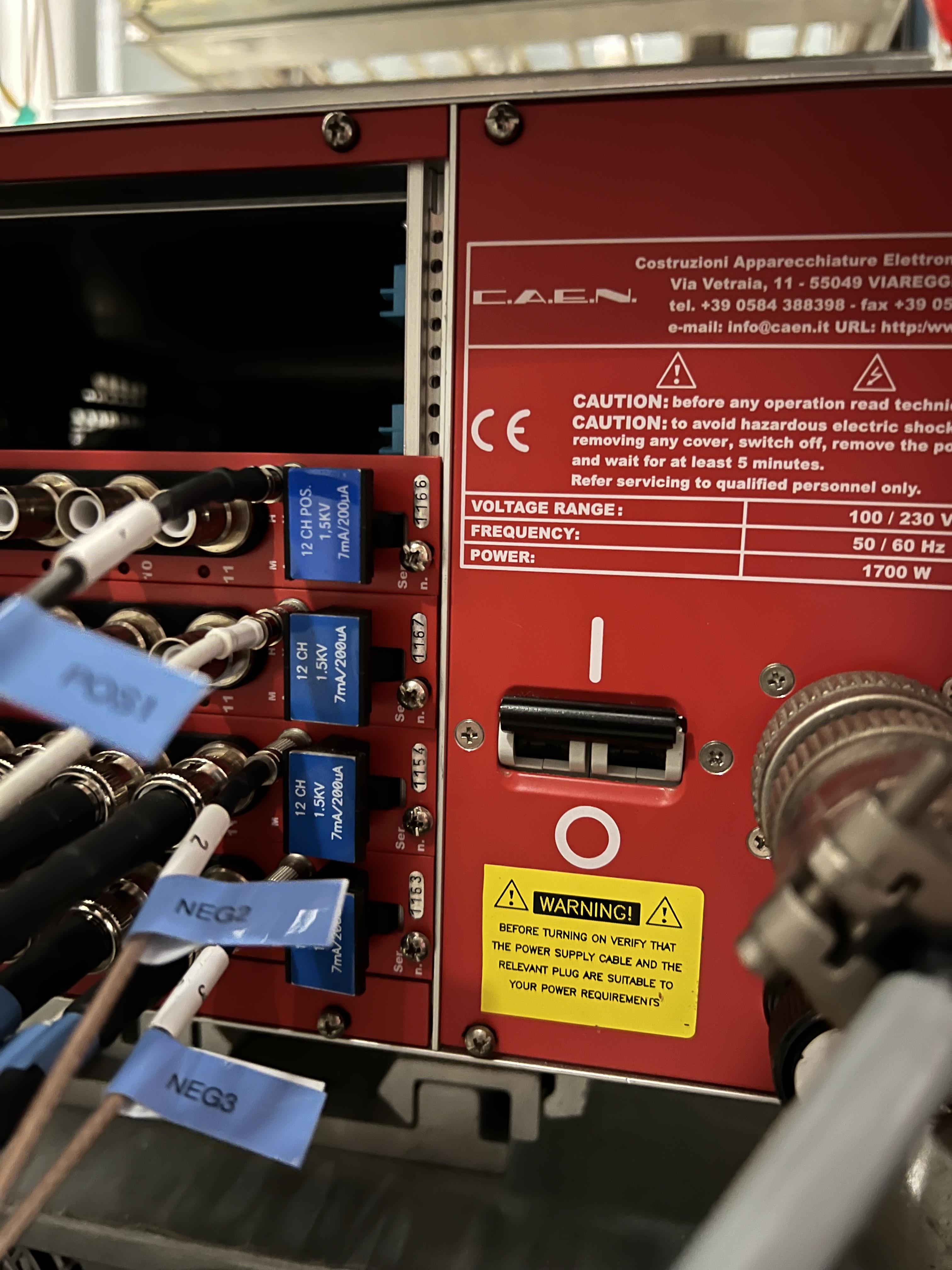
Fig. 4.46 This main power button for the JENSA CAEN power supply is found at its back, where the HV cards can be inserted.
4.8.5. How to Insert a New HV Card into the JENSA CAEN Power Supply
Prior to inserting a new HV card to the back of the JENSA CAEN power supply:
Make sure the new card has a 50 Ohm LEMO termintor connected to its “HVEN” input. Without this 50 Ohm LEMO terminator, the HV will be disabled and you will not be able to use that card.
If you are interested to provide an interlock on this new HV card, you need to talk to Ghulam Mujtaba and tell him to make a new relay connection (similar to the 4 HV cards we are already using) to where the 50 Ohm LEMO terminator is attached to.
There is a DIP switch on the HV card, which needs to be set properly before inserting the card into the power supply. The position of the keys in this DIP switch depends on the amount of the leakage currents from the detectors attached to the card. This, in turn, depends on the type of detectors whose bias is going to be provided by the new HV card.
If the detector’s maximum voltage is 1.5 kV and its leakage current is expected to be maximum of 1 mA: change the DIP switch on the card according to what is shown on the top of the image shown in Fig. 4.47.
If the detector’s maximum voltage is 1.5 kV and its leakage current is expected to be maximum of 200 \({\mu}A\): change the DIP switch on the card according to what is shown on the bottom of the image shown in Fig. 4.47.
When a key on the DIP switch is down, that switch in ON. If the key is up, the switch is OFF.
Make sure the main CAEN power supply is fully OFF (explained in subsection above) before inserting a new card.
With the power supply fully OFF, insert the card fully in and make sure it is correctly attached and secured.
Now, turn ON the power supply (Section 4.8.3).
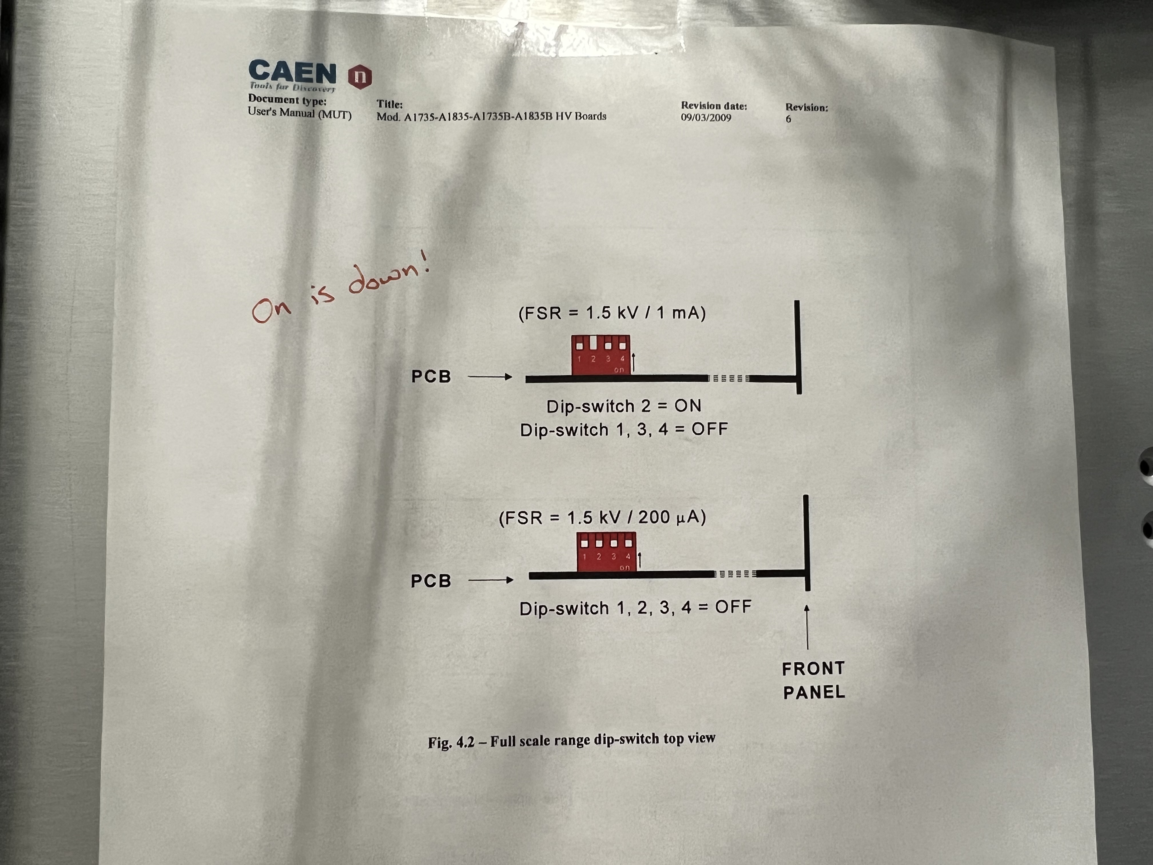
Fig. 4.47 The DIP switch on a HV card depends on the amount of the leakage currents drawn by any of the detectors attached to the card. If any of the detectors connected to the HV card is drawing too much leakage current (above what is permitted by the position of the DIP switch), the entire card will trip and all 12 channels will be disabled. Make sure these switches are set properly.
4.9. Long Term Shut Down Procedure
For a long-term shutdown, all valves are kept closed and all pumps are turned OFF (scroll pump will be turn OFF when switching to vent mode). The system should be vented but not open to the air (with all vent valves should be fully closed). The system should be left in the MAN mode of operation.
If the system owner/expert chooses to not leave the system vented, he/she can leave all high vacuum pumps OFF, switch to pump mode of operation, and keep the system under rough vacuum.